
How to generate inverted pulses using the ESP32 RMT module (Arduino & PlatformIO)
In our previous post ESP32 RMT pulse generation minimal example using Arduino & PlatformIO using the RMT peripheral. The pulses have a steady state (off state) of 0V and a pulse voltage of 3.3V.
If we want to generate inverted pulses, we have to invert the level entries in the pulseRMT array:
pulseRMT_example.cpp
static const rmt_item32_t pulseRMT[] = {
    {{{
      /*pulse duration=*/100, /*pulse level*/0,
      // After pulse, output 1
      0, 1
    }}} ,
};and additionally configure the RMT output when the pulse is finished using
example.cpp
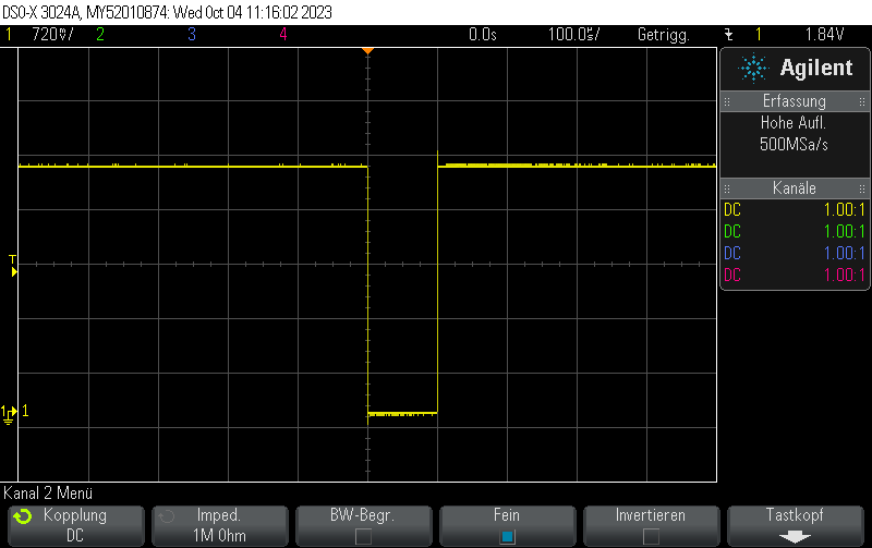
config.tx_config.idle_level = RMT_IDLE_LEVEL_HIGH;
config.tx_config.idle_output_en = true;This is how the pulse looks like:
Full example:
esp32_rmt_inverted_pulse.cpp
#include <Arduino.h>
#include <esp_log.h>
#include <driver/rmt.h>

// Output pulse train on D14
constexpr gpio_num_t rmtPin = GPIO_NUM_14;
constexpr rmt_channel_t RMT_TX_CHANNEL = RMT_CHANNEL_0;

static const rmt_item32_t pulseRMT[] = {
    {{{
      /*pulse duration=*/100, /*pulse level*/0,
      // After pulse, output 1
      0, 1
    }}},
};

void setup() {
  Serial.begin(115200);

  rmt_config_t config = RMT_DEFAULT_CONFIG_TX(rmtPin, RMT_TX_CHANNEL);
  config.clk_div = 80; // input clock 80 MHz => output clk 1 MHz
  config.tx_config.idle_level = RMT_IDLE_LEVEL_HIGH;
  config.tx_config.idle_output_en = true;

  ESP_ERROR_CHECK(rmt_config(&config));
  ESP_ERROR_CHECK(rmt_driver_install(config.channel, 0, 0));

}

void loop() {
  ESP_ERROR_CHECK(rmt_write_items(RMT_TX_CHANNEL, pulseRMT, sizeof(pulseRMT) / sizeof(rmt_item32_t), true));
  delay(10);
}platformio.ini
[env:esp32dev]
platform = espressif32
board = esp32dev
framework = arduino
monitor_speed = 115200Check out similar posts by category:
Arduino, C/C++, ESP8266/ESP32, PlatformIO
If this post helped you, please consider buying me a coffee or donating via PayPal to support research & publishing of new posts on TechOverflow