Minimal component count voltage-controlled duty cycle PWM circuit
When given a stimulus PWM e.g. from a microcontroller or other oscillator, this simple circuit allows using a capacitor’s time constant to generate
The main trick here is to use the Schottky diode D1 to discharge the capacitor quickly when the stimulus PWM is low, and charging it slowly via R1.
The values used here are for MHz-frequency PWMs. Choose a R-C time constant suitable for your PWM frequency (R1 / C1). A good place to start is with the R-C time constant at 0.5 * period with period = 1/frequency. In general, you want the capacitor to be almost fully charged when the positive duty cycle period is over. You can compute the time constant using Wolfram Alpha.
If you are using larger capacitors than ~10nF, you should add a resistor in series with D1 to avoid killing the MCU output stage by dumping all the capacitor’s energy into it. Compute the resistor so that the maximum allowable input current equals the capacitor charge voltage (= typically the MCU supply voltage) minus the minimum diode forward voltage, across the resistor. This is a conservative choice, but you should start from there.
Keep in mind that the charge voltage is not linear, therefore the resulting voltage-controlled duty cycle is not linear with input voltage.
In order to allow a high duty cycle PWM output, the stimulus PWM should have almost 100% duty cycle. There must be enough time in the off-duty-cycle to properly discharge the capacitor via the Schottky diode.
Consider adding hysteresis to the comparator to avoid output oscillation.
The choice of diode doesn’t matter too much. Schottky diodes should be preferred because they tend discharge the capacitor more completely within less time: A 1N4148 would only discharge the capacitor to Vf~=0.7V, whereas the rest of the charge would have to flow out via the resistor. With Schottky diodes, this forward voltage is just 0.3V, in effect allowing a higher maximum duty cycle.
A single R/C/D circuit can be used to power multiple comparators, allowing multiple channels of voltage controlled PWM.
Measurement results
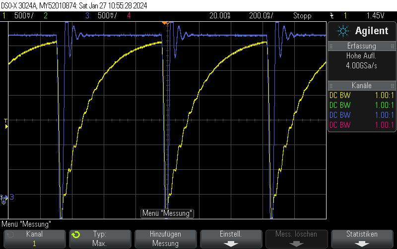
This is what it actually looks like. The voltage rise on the capacitor is fairly linear, it just appears to be oscillating due to inadequate effort being put into measuring this circuit. Keep in mind that this is not an ultra-precision circuit and in practice it’s not completely monotonous and certainly not linear in voltage.
The stimulus is given in blue. It’s a 4-bit 1.5MHz PWM with 15/16 duty cycle.
The capacitor voltage, which can be fed into the comparator, is shown in yellow.

