When you’re using some connector in your electronics project, you should always document the pinout – if you forget to do, you will absolutely 100% find yourself reverse-engineering your own pinout (Ask how I know). That’s a process that can easily take a few hours whereas you could have documented the pintout
Here’s a simple strategy that allows you to document the pinout.
1. Take a photo using your phone
It doesn’t have to look nice, we’re not creating an artwork here. The only requirements are that you can see the connector in its context and that you can see it :
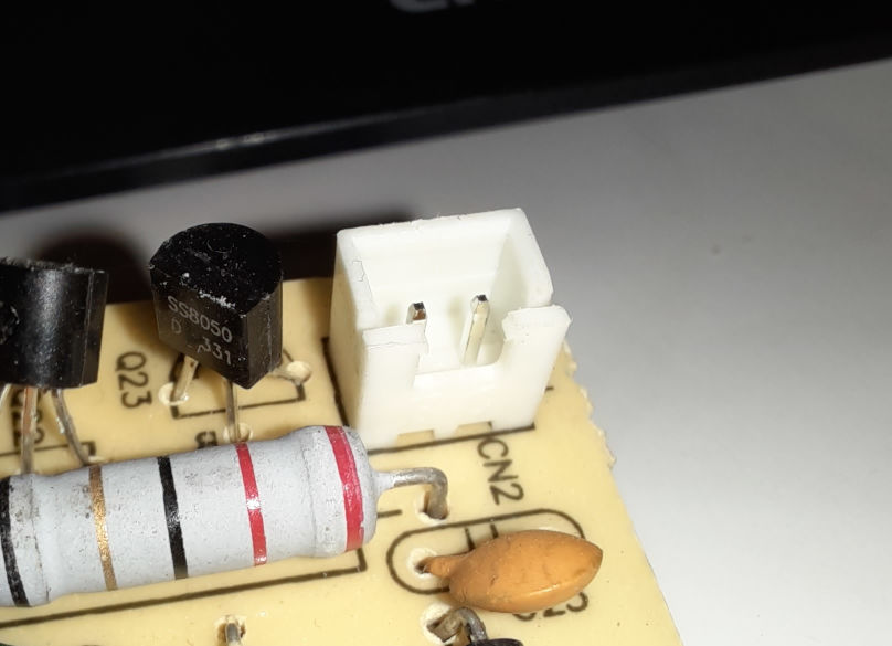
- For a connector on a PCB, ensure that you can see a few features around the connector from the board, and you can easily see notches or other features of the connector
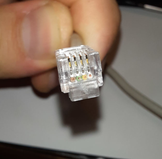
- For a connector on a cable, ensure that you can see the cable clip or any other cable
You can cut out the relevant section from the photo, but be sure to leave plenty of space around it (especially for PCB connectors) so you can
Example: PCB:
Example: Cable connector
2. Document the pins
Now load your picture into a drawing software. I mostly use draw.io which you can use from the Browser, but Inkscape also works totally fine. You can also use pixel image editing software like GIMP or Paint, but I recommend to instead use vector drawing software because it’s much easier to later modify some information when you use a vector graphics software. You can just use word, but DrawIO is typically just less cumbersome.
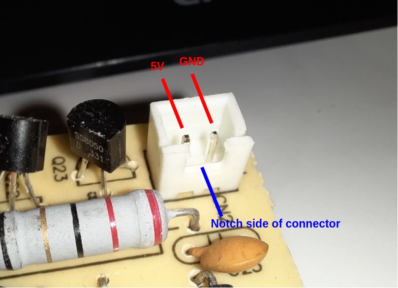
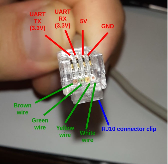
Place texts to annotate the function of pins and draw lines from the text to the actual pin. Use a signal color like red to make your annotations clearly visible.
Keep in mind that this is absolutely not about making it look good. As long as it’s clear which pin belongs to which annotation, always prefer quick to nice. Trying to make it look nice will not only cost you time but also distract you from the core task of making it unambiguous.
Also document special features like the clip of a connector, or a notch (indicating pin 1) in a different color.
Example: PCB:
Example: Cable connector
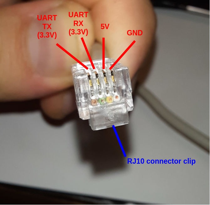
3. For cable connectors: Document the colors that are connected to the respective pins
You can skip this step if you want to document a connector on a PCB.
For cables, you want to make sure that when manufacturing e.g. a replacement cable that the correct color of wire is soldered/crimped/etc to the connector.
I suggest you do this using a different color like green.
Example:
4. Write down what exactly you’re documenting
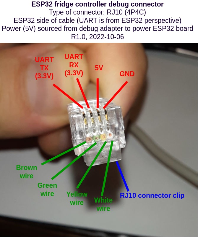
Typically above the photo, include metadata what it is you’re documenting. I suggest to always include that in the diagram (as opposed to just pasting the diagram into some Word document and writing it down there) because it makes it less likely that the diagram will get detached from its metadata. However, you can still write into any document where the diagram is included, there’s no reason why you have to avoid having the same information twice (sometimes it helps to spot mistakes after changes).
Always write down:
- The name of the project, e.g.
ESP32 fridge controller - The name of the connector within the project, e.g.
debug connector - The type of the connector, e.g.
Type of connector: RJ10 (4P4C). If applicable, also include information about where you bought the connector, manufacturer part number - Any information giving context to the annotations such as
UART is from ESP32 perspective - The revision number of the project, eg.
R1.0. If you don’t have a revision system, just call itR1.0, the next oneR2.0etc - The date when you created (or modified) the drawing, e.g.
2022-10-06. I recommend to use ISO8601 format (YYYY-MM-DD) exclusively to avoid month/day confusions.
Generally, more information is better. What you think is obvious now will be totally unclear tomorrow (or to someone else)
Example:
5. Save the result where you’ll find it when you need it most
I always recommend to save the connector documentation both as immutable file format (i.e. a format not intended for editing) such as PDF, PNG, JPG and using the original format from the drawing software (.xml or .drawio) for DrawIO,
If you are managing your project in git, upload both files to the git repository. If you are using a project management software such as redmine, upload your documentation there as well. You can absolutely upload it to multiple places, that’s why we used a date and a revision number above – the most important aspect is that it’s easy to find.
6. Further reading
You might also want to take a look at the following posts:
- This post is new so I don’t have any related posts so far 🙂