In order to instal tailscale, on any Ubuntu version, you can use the official tailscale install command:
sudo apt -y install curl apt-transport-https
curl -fsSL https://tailscale.com/install.sh | sh
In order to instal tailscale, on any Ubuntu version, you can use the official tailscale install command:
sudo apt -y install curl apt-transport-https curl -fsSL https://tailscale.com/install.sh | sh
libcamera-vid --width 1920 --height 1080 -f -t 10000000000
-t 10000000000 means to run for 10000000000 milliseconds (almost 4 months)
While trying to capture an image using raspistill, you see the following error message
ERROR: the system should be configured for the legacy camera stack
and no image is being produced
libcameraRecent versions of Raspbian use libcamera instead of the broadcom legacy camera API. You can capture an image using libcamera-still similarly to raspistill:
libcamera-still -o test.jpg
If you absolutely need raspistill specifically to work, you can still enable the legacy camera API using rpi-config:
sudo raspi-config
Go to:
and choose Yes to enable the legacy camera API.
On the Pi, run
libcamera-vid -t 0 --width 1920 --height 1080 --codec h264 --inline --listen -o tcp://0.0.0.0:8888
On the client, run
vlc tcp/h264://192.168.1.185:8888/
where 192.168.1.185 is the IP address of the Raspberry Pi.
The ESP32S2 has two 8-bit DACs.
The CHIP_PU (Chip PowerUp) pin on ESP32 family processors such as the ESP32S2 is equivalent to the EN (enable) or ~RST pin on other microcontrollers.
When CHIP_PU is pulled high (i.e. to 3.3V), the ESP32 is enabled and will run the firmware.
When CHIP_PU is pulled low (i.e. to GND), the ESP32 is disabled and shut down and will not run the firmware.
In other words, in most applications you want to connect a 10kOhm resistor from CHIP_PU to 3.3V and – if needed – a reset button from the CHIP_PU pin to GND. You can not operate the ESP32S2 without a pullup resistor . This is clearly stated in the ESP32S2 datasheet, section 2.2:
Note: Do not leave the CHIP_PU pin floating.
On the ESP32S2-WROOM-I module, the CHIP_PU is directly connected to the module’s EN pin wut
 Source: ESP32-S2 datasheet

Source: ESP32-C3 datasheet
The ESP32-C3 has 400 kBytes of integrated SRAM (16 kbytes cache).
Source: ESP32-C3 datasheet
void myTimerInterrupt() {
  // TODO Your code goes here
  // The following functions may be useful here:
  // Timer3.start(); // Start counting & clear counter
  // Timer3.stop(); // => stop counting but do not clear counter
  // Timer3.restart(); // => clear counter
  // Timer3.resume(); // => Start, without clearing counter
}

void setup()
{
  Timer3.initialize(20000);
  Timer3.attachInterrupt(myTimerInterrupt);
  Timer3.start();
}
You can use attachInterupt() with CHANGE to trigger on both RISING and FALLING flanks.
#define INTERRUPT_PIN 13 // Choose any pin with interrupt functionality here.

void myInterrupt() {
  // TODO Your code goes here.
}

void setup() {
  attachInterrupt(digitalPinToInterrupt(INTERRUPT_PIN), myInterrupt, CHANGE);
}
In setup(), use
attachInterrupt(digitalPinToInterrupt(23), myInterrupt, RISING);
to configure the interrupt on Teensy Pin 23 on the RISING edge.
Add this function, which will be called during the interrupt:
void myInterrupt() {
  // Your code goes here
}
While flashing an STM32 using st-flash using a command like
st-flash write build/firmware.bin 0x8000000
you see an error message like
2022-02-12T01:31:34 ERROR flash_loader.c: flash loader run error
2022-02-12T01:31:34 ERROR common.c: stlink_flash_loader_run(0x8000000) failed! == -1
See below for a full error log
Most likely your STM32 is locked (readout protection). Use OpenOCD to unlock it, see How to unlock STM32F0x using OpenOCD for an example. Adjust to your STM32 family as needed.
st-flash logst-flash 1.6.1 2022-02-12T01:31:34 INFO common.c: F0xx small: 4 KiB SRAM, 16 KiB flash in at least 1 KiB pages. file build/mom.bin md5 checksum: da211df7131de9de15f3b6c7a96176dd, stlink checksum: 0x000d0d03 2022-02-12T01:31:34 INFO common.c: Attempting to write 11108 (0x2b64) bytes to stm32 address: 134217728 (0x8000000) 2022-02-12T01:31:34 INFO common.c: Flash page at addr: 0x08000000 erased 2022-02-12T01:31:34 INFO common.c: Flash page at addr: 0x08000400 erased 2022-02-12T01:31:34 INFO common.c: Flash page at addr: 0x08000800 erased 2022-02-12T01:31:34 INFO common.c: Flash page at addr: 0x08000c00 erased 2022-02-12T01:31:34 INFO common.c: Flash page at addr: 0x08001000 erased 2022-02-12T01:31:34 INFO common.c: Flash page at addr: 0x08001400 erased 2022-02-12T01:31:34 INFO common.c: Flash page at addr: 0x08001800 erased 2022-02-12T01:31:34 INFO common.c: Flash page at addr: 0x08001c00 erased 2022-02-12T01:31:34 INFO common.c: Flash page at addr: 0x08002000 erased 2022-02-12T01:31:34 INFO common.c: Flash page at addr: 0x08002400 erased 2022-02-12T01:31:34 INFO common.c: Flash page at addr: 0x08002800 erased 2022-02-12T01:31:34 INFO common.c: Finished erasing 11 pages of 1024 (0x400) bytes 2022-02-12T01:31:34 INFO common.c: Starting Flash write for VL/F0/F3/F1_XL core id 2022-02-12T01:31:34 INFO flash_loader.c: Successfully loaded flash loader in sram 2022-02-12T01:31:34 ERROR flash_loader.c: flash loader run error 2022-02-12T01:31:34 ERROR common.c: stlink_flash_loader_run(0x8000000) failed! == -1 stlink_fwrite_flash() == -1
You can use st-flash like this to flash a firmware file to the STM32:
st-flash write build/firmware.bin 0x8000000
openocd -f interface/stlink-v2.cfg -f target/stm32f0x.cfg -c "init" -c "halt" -c "stm32f1x lock 0" -c "reset halt" -c "exit"
This will activate flash readout protection level 1 which means you won’t be able to readout or re-write the flash. You can still perform a chip erase which will clear the readout protection – for example to flash a new firmware.
openocd -f interface/stlink-v2.cfg -f target/stm32f0x.cfg -c "init" -c "halt" -c "stm32f1x unlock 0" -c "reset halt" -c "exit"
After that, you need to physically remove power from the device in order for the reset to take effect.
Note the stm32f1x is no typo. OpenOCD uses the same backend for STM32F1x and STM32F0x.
Example output:
Open On-Chip Debugger 0.11.0-rc2
Licensed under GNU GPL v2
For bug reports, read
        http://openocd.org/doc/doxygen/bugs.html
WARNING: interface/stlink-v2.cfg is deprecated, please switch to interface/stlink.cfg
Info : auto-selecting first available session transport "hla_swd". To override use 'transport select <transport>'.
Info : The selected transport took over low-level target control. The results might differ compared to plain JTAG/SWD
Info : clock speed 1000 kHz
Info : STLINK V2J24S4 (API v2) VID:PID 0483:3748
Info : Target voltage: 3.296172
Info : stm32f0x.cpu: hardware has 4 breakpoints, 2 watchpoints
Info : starting gdb server for stm32f0x.cpu on 3333
Info : Listening on port 3333 for gdb connections
Info : device id = 0x10006444
Info : flash size = 16kbytes
stm32x unlocked.
INFO: a reset or power cycle is required for the new settings to take effect.

Info : Unable to match requested speed 1000 kHz, using 950 kHz
Info : Unable to match requested speed 1000 kHz, using 950 kHz
target halted due to debug-request, current mode: Thread
xPSR: 0xc1000000 pc: 0x080000c0 msp: 0x20000400
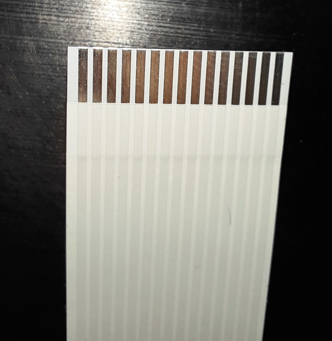
The Raspberry Pi DSI display connector (for example the DSI display cable that comes with the Raspberry Pi 7″ display) has a pin pitch of 1.0mm:
Just use the official install command from the tailscale website:
curl -fsSL https://tailscale.com/install.sh | sh
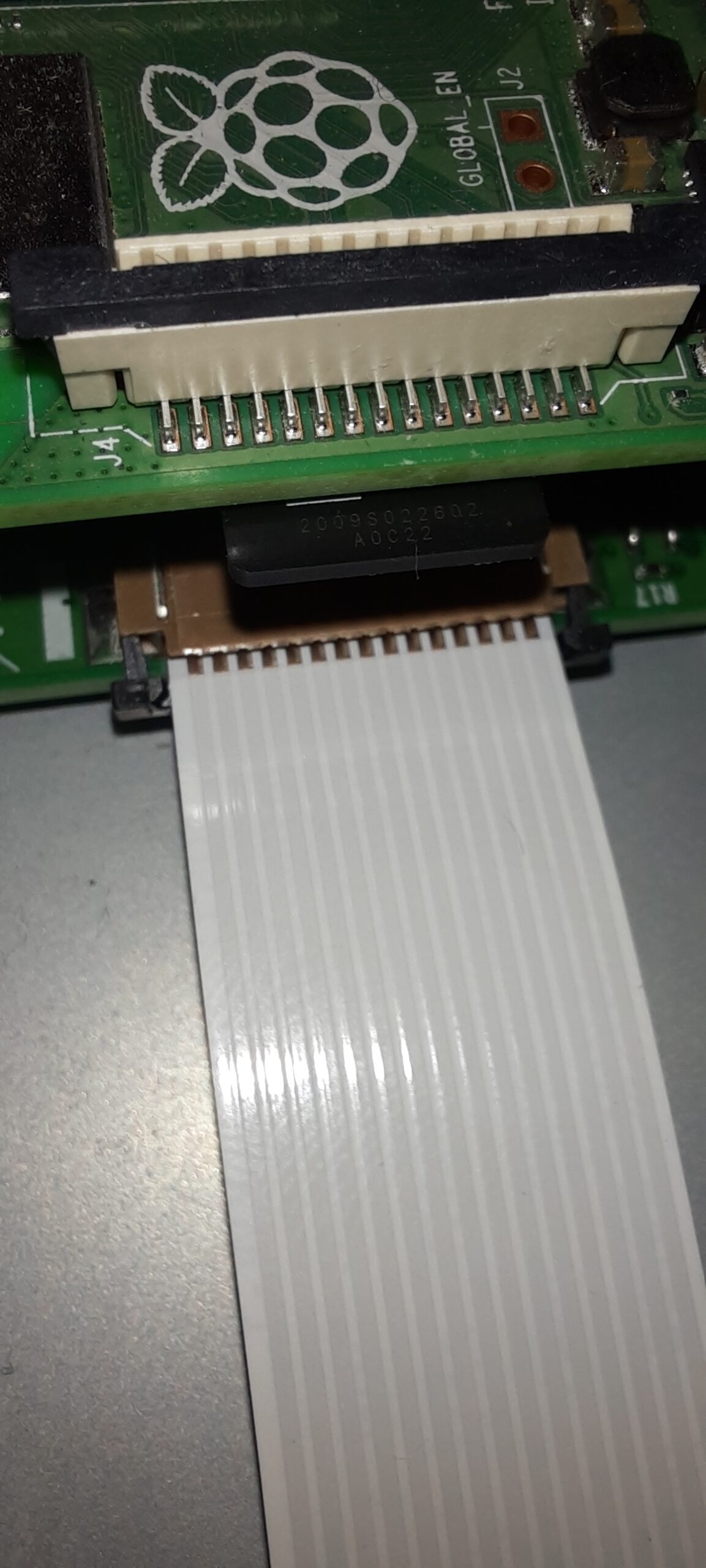
First, mount the Raspberry Pi on top of the display PCB on the back of the display.
On the bottom (display) PCB, the silver contacts of the cable should be at the top (facing the Raspberry Pi):
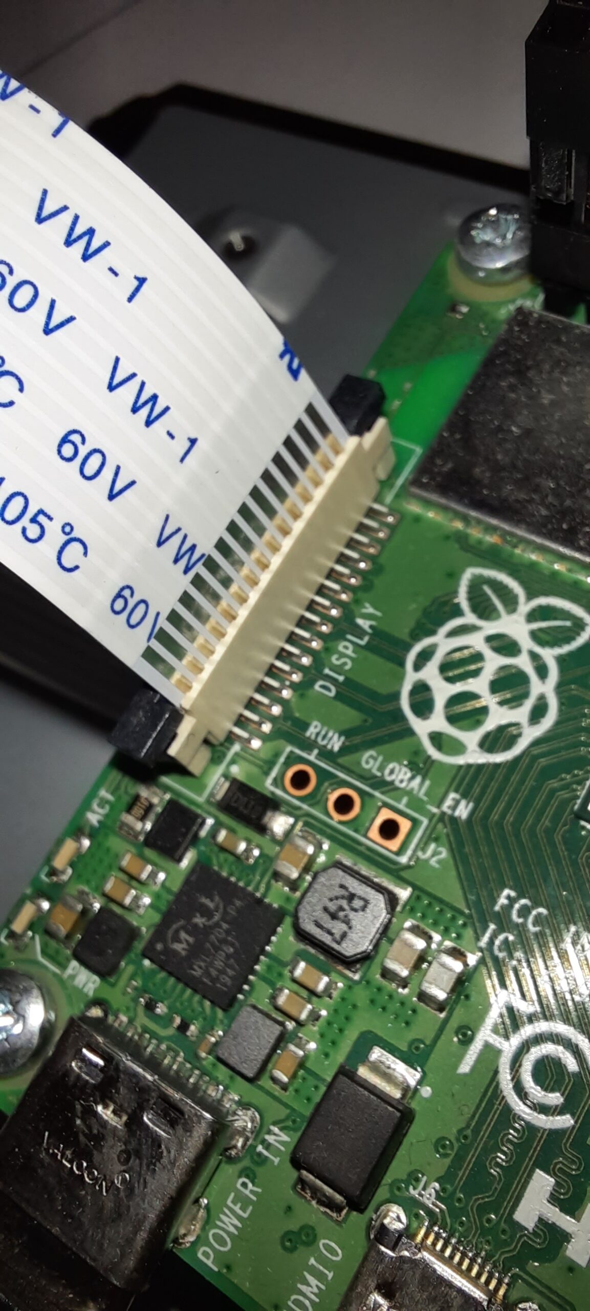
On the Raspberry Pi, the silver contacts should face towards the USB connectors:
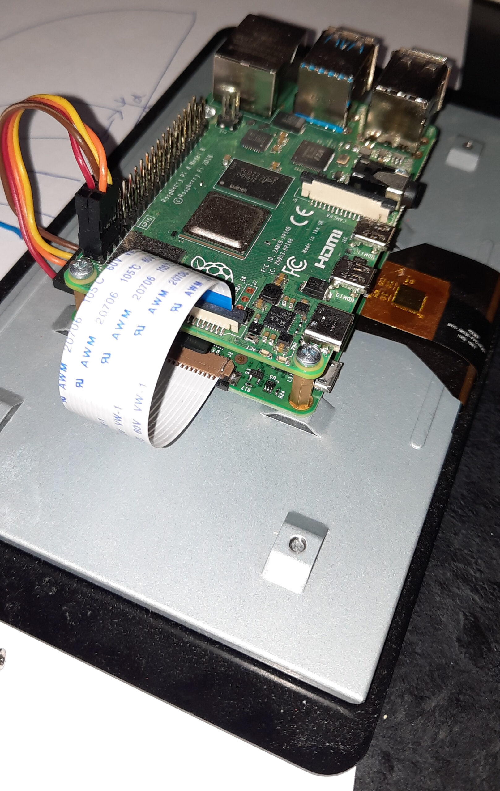
Overall, it should look like this:
First, install OctoPi to the SD card – for example, using rpi-imager: How to install OctoPi using rpi-imager
Open the boot partition on the OctoPi SD card and create a file wpa_supplicant.conf there, with the following content:
country=de
update_config=1
ctrl_interface=/var/run/wpa_supplicant

network={
   scan_ssid=1
   ssid="MyWifi"
   psk="abc123abc"
}
Always set the correct country code at the top ! If you don’t set it correctly, it won’t work!
Set ssid to the name of the wireless network.
Set psk to the wifi password.