Embedded

ArduinoJSON: How to fix 1 or 0 being printed instead of true/false

volatile bool value = true;

DynamicJsonDocument json(1024);
json["ok"] = value;
serializeJson(json, Serial);

This will print {"ok": 1} instead of {"ok": true} due to value being declared volatile (it works with just bool value, it does not work with volatile bool value).

In order to force {"ok": true}, just case value to bool:

json["ok"] = (bool)value;

Full example

volatile bool value = true;

DynamicJsonDocument json(1024);
json["ok"] = (bool)value;
serializeJson(json, Serial);


Posted by Uli Köhler in Arduino, Embedded, PlatformIO

FreeRTOS mutex minimal example

This is how you create and use a mutex in FreeRTOS:

Includes:

#include <freertos/semphr.h>


Global declaration

SemaphoreHandle_t myMutex;

Initialization code

Call this once, before using it:

myMutex = xSemaphoreCreateMutex();

How to lock & unlock the mutex

// Wait a maximum of 10ms to lock the mutex
if(xSemaphoreTake(myMutex, 10 / portTICK_PERIOD_MS) == pdTRUE) {
   // Success locking the mutex
   // TODO: Your code goes here!
   // Unlock the mutex!
   xSemaphoreGive(myMutex);
} else {
   // Failed to lock the mutex within timeout
   // DO NOT use the resource protected by the mutex
   // DO NOT unlock (xSemaphoreGive) !
}


Posted by Uli Köhler in Embedded, FreeRTOS, PlatformIO

ESPAsyncWebserver basic ArduinoJSON handler example

server.on("/api/test", HTTP_GET, [](AsyncWebServerRequest *request) {
      // Respond with JSON {"status": "ok"}
      AsyncResponseStream *response = request->beginResponseStream("application/json");
      DynamicJsonDocument json(1024);
      json["status"] = "ok";
      serializeJson(json, *response);
      request->send(response);
});


Posted by Uli Köhler in ESP8266/ESP32, Networking

ESPAsyncWebserver handler example with int query argument

This example is based on our basic example and shows how to use an int query parameter, e.g. http://192.168.1.112/api/test?param=2

server.on("/api/test", HTTP_GET, [](AsyncWebServerRequest *request) {
      int param = request->getParam("param")->value().toInt();
      // TODO: Do something with param!

      // Respond with JSON {"status": "ok"}
      AsyncResponseStream *response = request->beginResponseStream("application/json");
      DynamicJsonDocument json(1024);
      json["status"] = "ok";
      json["param"] = param;
      serializeJson(json, *response);
      request->send(response);
});


Posted by Uli Köhler in ESP8266/ESP32, Networking

How to print all preprocessor flags in PlatformIO

In order to show the values of all preprocessor flags, set this in platformio.ini:

build_flags = -E -dM

Now rebuild and you’ll see an error message like

Linking .pio/build/ESP32/firmware.elf
.pio/build/ESP32/src/main.cpp.o: file not recognized: File format not recognized
collect2: error: ld returned 1 exit status
*** [.pio/build/ESP32/firmware.elf] Error 1

This error is expected since GCC will not produce object files as output but preprocessor output definitions!

Now open the respective “object” files in your text editor:

code .pio/build/ESP32/src/main.cpp.o

where ESP32 is the name of your build configuration in platformio.ini. You will see all the definitions like this:

#define VSPI 3
#define XTENSA_HWCIDVERS_T1030_3 12
#define GPIO_PIN19_INT_TYPE 0x00000007
#define CONFIG_LWIP_MAX_RAW_PCBS 16
#define XTENSA_HWVERSION_RD_2012_4 240004
#define SPI_CLOCK_DIV32 0x013c1001
#define VALUE_GET_FIELD(_r,_f) (((_r) >> (_f ##_S)) & (_f))
#define GPIO_FUNC40_IN_INV_SEL (BIT(6))
#define GPIO_SIG31_IN_SEL (BIT(7))
#define ETS_RWBLE_NMI_SOURCE 9
#define RTC_IO_PDAC1_DAC_S 19
#define LWIP_HOOK_TCP_ISN lwip_hook_tcp_isn
#define RTC_IO_PDAC1_DAC_V 0xFF
#define XCHAL_INT30_TYPE XTHAL_INTTYPE_EXTERN_EDGE
#define _ETS_SET_INTLEVEL(intlevel) ({ unsigned __tmp; __asm__ __volatile__( "rsil   %0, " _ETSTR(intlevel) "\n" : "=a" (__tmp) : : "memory" ); })
#define B11101001 233
#define SPIWP_IN_IDX 4
#define MEMP_NUM_API_MSG MEMP_NUM_TCPIP_MSG_API
#define GPIO_FUNC74_IN_INV_SEL_M (BIT(6))
// ...


Posted by Uli Köhler in Electronics, Embedded, PlatformIO

How to add preprocessor build flags in PlatformIO

In order to define a preprocessor build flag in PlatformIO, add it to build_flags in platformio.ini, prefixing it with -D:

build_flags = -DQUICKSPI_DEBUG_WRITES

or, in order to define it to a specific value, use

build_flags = -DQUICKSPI_DEBUG_WRITES=1


Posted by Uli Köhler in C/C++, PlatformIO

Diagnosing I2C issues using an oscilloscope: Slow rising edge, fast falling edge

If your I2C clock and/or data signal look like this:

in other words, if the rising edge is very slow and not sharp compared to the you are facing an issue with a pull-up resistor which is too large. A good point to start is to use a pull-up resistor 1/4 the value of the pull-up currently installed on your board. If you don’t have any pull-up on your board, start with a 2.2 kOhm pull-up resistor.

As a hotfix, you can operate I2C at slower speed like 100 kHz or even slower (like 10 kHz). This will temporarily fix the issue and depending on your application there might not be any need to go faster than that.

Posted by Uli Köhler in Compliance, Electronics, Embedded

How should the SPI SCLK look on the oscilloscope?

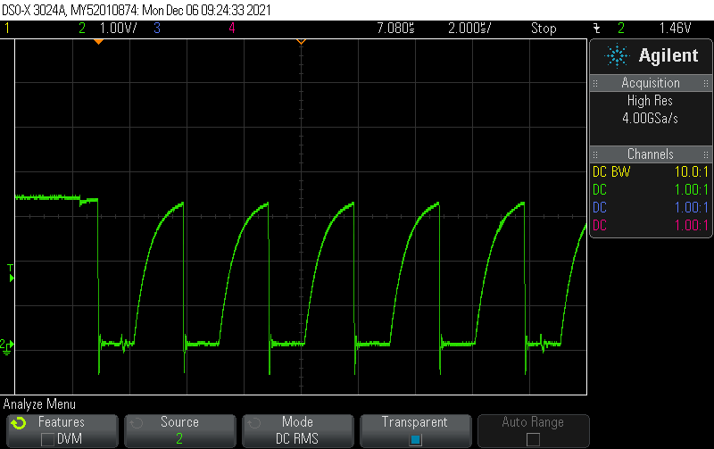
SPI is typically used at 1-20MHz clock frequency. Start with setting the oscilloscope to 2 microseconds per division and 2V per division. Hence, set your scope. Set the trigger to edge mode to trigger at half the supply voltage (e.g. 1.65V for 3.3V supply voltage).The following example is SPI running at 1 MHz on a supply of 3.3V:

Always start by measuring SCLK, to verify both a valid signal clock and your measurement setup. The signal should always look like this:

The first aspect to verify here is that the SCLK should be mostly symmetric (50% duty cycle) and running continously throughout each SPI data transfer. The frequency should typically not change during a single SPI transfer.

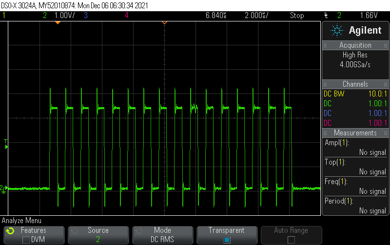
SPI tolerates a significant amount of overshoot. In case you have signal integrity issues, you can typically just reduce the clock speed. In order to have a closer look on the signal integrity aspects, zoom in so you see just one clock cycle.


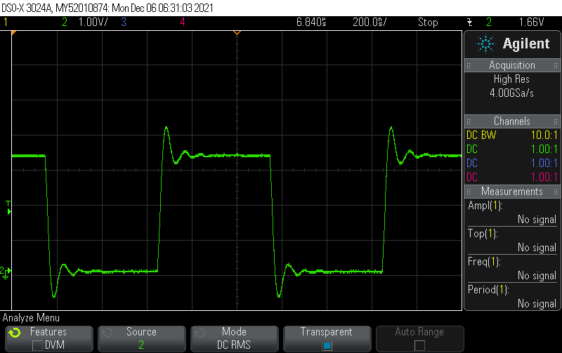
The amount of overshoot you see in our example is totally fine. What you should look for here is that both the rising and falling edge should be reasonably sharp and the 0 and 1 bits should be clearly visible.

Regarding overshoot/undershoot, a good rule of thumb is that during the 1 bit, the voltage should never be less than 0.8 times the steady-state voltage during the one bit (see below for red and blue markers):

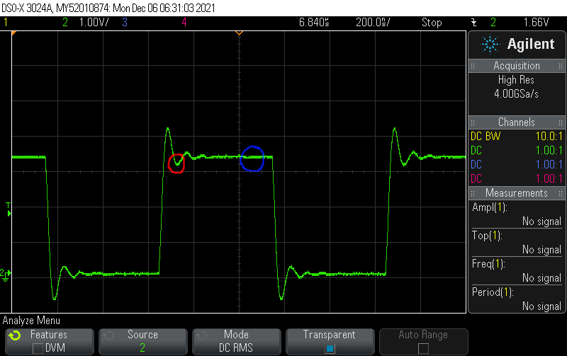
Similarly, during the 0 bit, the voltage should never be less than 0.2 times the steady-state voltage during the one bit

Note that not only does your PCB affect the signal integrity – your measurement setup (oscilloscope & probe) affects them to some extent as well.

Posted by Uli Köhler in Compliance, Electronics, Embedded

What is the FreeRTOS equivalent to Arduino’s delay()?

Instead of Arduino’s

delay(5); // delay for five milliseconds

use this in FreeRTOS:

vTaskDelay(5 / portTICK_PERIOD_MS);
Posted by Uli Köhler in Arduino, Electronics, Embedded, FreeRTOS

How to add FreeRTOS task (“thread”) to any PlatformIO project

Most PlatformIO default configurations already have FreeRTOS enabled – they just don’t use it.

In order to start a new FreeRTOS “thread” (called task in FreeRTOS-speak), first add these includes:

#include <freertos/FreeRTOS.h>
#include <freertos/task.h>

Now add the task function and handle:

TaskHandle_t myTaskHandle;
void MyTask( void * parameter )
{
    for(;;)
    {
       // TODO Task code goes here
    }
    // if you ever exit the loop, this is here to clean up the resources
    vTaskDelete( NULL );
}

then start the task using this code once, for example in your main function:

// Start MyTask thread
xTaskCreate(
    MyTask, // Task function
    "MyTask", // Name
    10000, // Stack size
    NULL, // Parameter
    1, // Priority
    &myTaskHandle);

Also see our new post on how to use xTaskCreateStatic() to use statically allocated instead of dynamically allocated stack memory for the task: FreeRTOS task with static stack memory (xTaskCreateStatic) example

Posted by Uli Köhler in C/C++, Electronics, Embedded, FreeRTOS, PlatformIO

How to add library dependency from local filesystem in PlatformIO

If you want to add a library dependency to lib_deps where the library is from the local file system, just add the full path to lib_deps

lib_deps =
    /home/user/MyCustomLib

This is really handy when developing libs since it allows you to just save changes in the source code and rebuild your main project without any need to publish and update the package first.

Note that you need to Clean and then Build or Upload in order to update the files from the local directory. PlatformIO will cache them unless you Clean and then rebuild!

Posted by Uli Köhler in PlatformIO

What is the value of portTICK_PERIOD_MS and configTICK_RATE_HZ on the ESP32 using PlatformIO?

When you use PlatformIO with the Arduino framework in its default configuration on the ESP32, configTICK_RATE_HZ is set to 1000. In other words, FreeRTOS has a default tick frequency of 1kHz. This is defined in sdkconfig.h:

#define CONFIG_FREERTOS_HZ 1000

Hence portTICK_PERIOD_MS is 1. In my opinion, a tick rate of 1kHz is a sane configuration for most usecases.

I found the value by using the following code on an ESP32:

Serial.println("Timing: ");
Serial.println(portTICK_PERIOD_MS);
Serial.println(configTICK_RATE_HZ);


Posted by Uli Köhler in Arduino, Electronics, Embedded, ESP8266/ESP32, FreeRTOS, PlatformIO

How to read 8-bit I2C register using Arduino Wire library: A minimal example

The following code demonstrates how to read a register that is 1 byte (8 bits) long over I2C. It will work with almost all I2C devices like EEPROMs, ADCs and others, provided you have the correct. Note that some devices like the LAN9303 have a slightly different addressing scheme or other peculiarities. In my opinion, it’s most efficient to just try out the standard way of reading a register and start from there.

Note that this code does not implement error handling for the sake of simplicity. Additionally, we wait for data using delay() instead of Wire.available(). This is a minimal example so it creates minimal confusion for the reader. We will provide a full example with error handling in a followup post.

const uint8_t SLAVE_I2C_ADDRESS = 0b1010;
const uint16_t SLAVE_I2C_REGISTER_ADDRESS = 0x50;

Wire.beginTransmission(SLAVE_I2C_ADDRESS);
Wire.write(SLAVE_I2C_REGISTER_ADDRESS);
Wire.endTransmission();
Wire.requestFrom(SLAVE_I2C_ADDRESS, 1); // This register is 8 bits = 1 byte long
delay(2); // Wait for data to be available
// Read directly into an uint8_t
uint8_t buf = (uint8_t)Wire.read();
// Print register value
Serial.printf("Register value: %02x\r\n", buf);

Also see:

Posted by Uli Köhler in Arduino, C/C++, Electronics, Embedded, PlatformIO

How to read 16-bit I2C register using Arduino Wire library: A minimal example

The following code demonstrates how to read a register that is 2 bytes (16 bits) long over I2C. It will work with almost all I2C devices like EEPROMs, ADCs and others, provided you have the correct. Note that some devices like the LAN9303 have a slightly different addressing scheme or other peculiarities. In my opinion, it’s most efficient to just try out the standard way of reading a register and start from there.

Note that this code does not implement error handling for the sake of simplicity. Additionally, we wait for data using delay() instead of Wire.available(). This is a minimal example so it creates minimal confusion for the reader. We will provide a full example with error handling in a followup post.

Option 1: Reading the register into an uint16_t (recommended)

const uint8_t SLAVE_I2C_ADDRESS = 0b1010;
const uint16_t SLAVE_I2C_REGISTER_ADDRESS = 0x50;

Wire.beginTransmission(SLAVE_I2C_ADDRESS);
Wire.write(SLAVE_I2C_REGISTER_ADDRESS);
Wire.endTransmission();
Wire.requestFrom(SLAVE_I2C_ADDRESS, 2); // This register is 16 bits = 2 bytes long
delay(5); // Wait for data to be available
// Read directly into an uint32_t
uint16_t buf;
Wire.readBytes((uint8_t*)&buf, 2);
// Print register value
Serial.printf("Register value: %04x\r\n", __builtin_bswap16(buf));

For an explanation on why we need __builtin_bswap16(), see How to print 16-bit uint16_t as four hex digits in Arduino

Option 2: Reading the register into an uint8_t array

const uint8_t SLAVE_I2C_ADDRESS = 0b1010;
const uint16_t SLAVE_I2C_REGISTER_ADDRESS = 0x50;

Wire.beginTransmission(SLAVE_I2C_ADDRESS);
Wire.write(SLAVE_I2C_REGISTER_ADDRESS);
Wire.endTransmission();
Wire.requestFrom(SLAVE_I2C_ADDRESS, 2); // This register is 16 bits = 2 bytes long
delay(5); // Wait for data to be available
// Read into a 2-byte buffer
uint8_t buf[2];
Wire.readBytes(buf, 2);
// Print register value
Serial.printf("Register value: %02x%02x\r\n", buf[0], buf[1]);

Also see:

Posted by Uli Köhler in Arduino, C/C++, Electronics, Embedded, PlatformIO

How to read 32-bit I2C register using Arduino Wire library: A minimal example

The following code demonstrates how to read a register that is 4 bytes (32 bits) long over I2C. It will work with almost all I2C devices like EEPROMs, ADCs and others, provided you have the correct. Note that some devices like the LAN9303 have a slightly different addressing scheme or other peculiarities. In my opinion, it’s most efficient to just try out the standard way of reading a register and start from there.

Note that this code does not implement error handling for the sake of simplicity. Additionally, we wait for data using delay() instead of Wire.available(). This is a minimal example so it creates minimal confusion for the reader. We will provide a full example with error handling in a followup post.

Option 1: Reading the register into an uint32_t (recommended)

const uint8_t SLAVE_I2C_ADDRESS = 0b1010;
const uint16_t SLAVE_I2C_REGISTER_ADDRESS = 0x50;

Wire.beginTransmission(SLAVE_I2C_ADDRESS);
Wire.write(SLAVE_I2C_REGISTER_ADDRESS);
Wire.endTransmission();
Wire.requestFrom(SLAVE_I2C_ADDRESS, 4); // This register is 32 bits = 4 bytes long
delay(5); // Wait for data to be available
// Read directly into an uint32_t
uint32_t buf;
size_t actually_read = Wire.readBytes((uint8_t*)&buf, 4);
// Print register value
Serial.printf("Register value: %08lx\r\n", __builtin_bswap32(buf));

For an explanation on why we need __builtin_bswap32(), see How to print 32-bit uint32_t as eight hex digits in Arduino

Option 2: Reading the register into an uint8_t array

const uint8_t SLAVE_I2C_ADDRESS = 0b1010;
const uint16_t SLAVE_I2C_REGISTER_ADDRESS = 0x50;

Wire.beginTransmission(SLAVE_I2C_ADDRESS);
Wire.write(SLAVE_I2C_REGISTER_ADDRESS);
Wire.endTransmission();
Wire.requestFrom(SLAVE_I2C_ADDRESS, 4); // This register is 32 bits = 4 bytes long
delay(5); // Wait for data to be available
// Read into a 4-byte buffer
uint8_t buf[4];
size_t actually_read = Wire.readBytes(buf, 4);
// Print register value
Serial.printf("Register value: %02x%02x%02x%02x\r\n", buf[0], buf[1], buf[2], buf[3]);

Also see:

Posted by Uli Köhler in Arduino, C/C++, Electronics, Embedded, PlatformIO

Which strap resistor value to use for LAN9303?

The LAN9303 datasheet currently does explictly specify a strapping resistor value. However, the evalboard schematic effectively uses a 10kΩ resistor when strapping to GND or a 20kΩ resistor when strapping to VDD. I have experimentally verified that 10kOhm strapping resistors work when strapping to GND. On my boards, I do not explicitly strap to VDD because most strappable pins have internal pull-ups and I don’t need to use the LEDs.

Hence, my recommendation is to strap the LAN9303 using 10kΩ resistors.

Posted by Uli Köhler in Electronics, Embedded, Networking

How to get the LAN9303 into I2C managed mode

In order to set the LAN9303 into I2C managed mode where you can configure the chip using I2C,  strap MNGT1 to 1 and strap MNGT0 to 0. Since the MNGT[1:0] strap pins have an internal pull-up, you only need to strap MNGT0 (pin 26 on the QFN package) to GND using a 10kΩ resistor from this pin to GND.

Posted by Uli Köhler in Electronics, Embedded, Networking

How to access LAN9303 registers over I2C using Arduino / PlatformIO

The LAN9303 has some peculiarities when accessing its registers. This post will not cover indirect register access but only access to the registers which are directly accessible over I2C. Note that the prerequisite for this is to configure the LAN9303 into a mode where management over the I2C slave interface is enabled. See How to get the LAN9303 into I2C managed mode for more info on how to do that.

The main point to take away is that you do not write the register offset from the datasheet (such as 0x50 for the Chip ID and revision register) in the I2C address byte but the address divided by 4 (0x50 >> 2 == 0x14). This is evidenced by figure 8-8 from the datasheet, copyright Microchip, listing the address byte as A[9:2] as opposed to the standard A[7:0]:


Example on how to access the register at offset 0x50 (Chip ID and revision register) in Arduino using the Wire library:

const uint8_t LAN9303_I2C_ADDRESS = 0b1010;
const uint16_t LAN9303_CHIPID_REV_Register = 0x50;

Wire.beginTransmission(LAN9303_I2C_ADDRESS);
Wire.write(LAN9303_CHIPID_REV_Register >> 2);
Wire.endTransmission();
Wire.requestFrom(LAN9303_I2C_ADDRESS, 4); // This register is 32 bits = 4 bytes long
delay(5); // Wait for data to be available

// Read directly into an uint8_t
uint32_t buf;
size_t actually_read = Wire.readBytes((uint8_t*)&buf, 4);
// Check if we have received all 4 bytes
if(actually_read != 4) {
    Serial.println("Did not read enough bytes");
}

// Print register value
Serial.printf("LAN9303 Chip ID and revision: %08lx\r\n", __builtin_bswap32(buf));

This will print

LAN9303 Chip ID and revision: 93030001

in other words: Chip ID = 0x9303, revision = 0x0001


Posted by Uli Köhler in Arduino, C/C++, Electronics, Embedded, Networking, PlatformIO

How to print 64-bit uint64_t as sixteen hex digits in Arduino

When using Arduino, you often want to print the hex value of a 64-bit value such as a uint64_t, consisting of sixteen hex digits. For example, if you have uint64_t val = 169557370125;, you intend to print 000000277a68250d.

In Arduino you can do that using Serial.printf() with %08lx08lx as format specifier, splitting the uint64_t in two uint32_t instances and printing those one after another:

Serial.printf("%08lx%08lx\r\n",
    ((uint32_t)((val >> 32) & 0xFFFFFFFF)),
    ((uint32_t)(val & 0xFFFFFFFF)));


See How to print 32-bit uint32_t as eight hex digits in Arduino for more information on what %x means and why we need to use the 08 in %08x as a printf format specifier.

Posted by Uli Köhler in Arduino, Electronics, Embedded, PlatformIO