STM32

How to exit/reset STM32 DFU bootloader

Both dfu-util and dfu-tool can flash firmware, but their current versions can’t reset the STM32 from DFU mode to run the application.

I found that using MicroPython’s pydfu.py is able to reset the. Note that currently I use pydfu.py only for resetting, not for flashing (but that might change in the future).

Download using

wget https://raw.githubusercontent.com/micropython/micropython/master/tools/pydfu.py

Install the PyUSB dependency using

sudo pip3 install pyusb

And then reset the STM32 in DFU mode:

python3 pydfu.py -x


Posted by Uli Köhler in STM32

How to flash Marlin on BigTreeTech Octopus V1 using debug adapter

In order to flash the Bigtreetech Octopus V1 using my STLinkv2 debug adapter, I needed. First we need to note that the first 32k of flash memory are occupied by the bootloader (0x08000000 to 0x08008000). So we need to flash the firmware at address 0x08008000. By default, this is not configured correctly in Marlin.

Open ini/stm32f4.ini and edit the [env:BIGTREE_OCTOPUS_V1]:

[env:BIGTREE_OCTOPUS_V1]
platform           = ${common_stm32.platform}
extends            = stm32_variant
board              = marlin_BigTree_Octopus_v1
board_build.offset = 0x8000
board_upload.offset_address = 0x08008000
build_flags        = ${stm32_variant.build_flags}
                     -DSTM32F446_5VX -DUSE_USB_HS_IN_FS
upload_protocol = stlink

Note that you absolutely need to re-flash the bootloader in case you accidentally flashed with the old configuration. Follow the official documentation in order to flash the bootloader. I flash usin STM32CubeProgrammer 2.7.0 (2.8.0 does not work) on both Linux and Windows.

The [env:BIGTREE_OCTOPUS_V1_USB] will be updated automatically as it includes [env:BIGTREE_OCTOPUS_V1]

Posted by Uli Köhler in 3D printing, Electronics, STM32

How to fix PlatformIO serial monitor scrambled output

Problem:

When using the Monitor function of platformIO, you see strange characters instead of strings being printed, for example:

)�
�␜ܠ��J��1��1!y��!���!��

Solution:

This issue almost always appears due to the Monitor function using the wrong UART speed. You can see from the log in our screenshot above:

--- Miniterm on /dev/ttyUSB0  9600,8,N,1 ---

that PlatformIO is using 9600 baud in this case – but your microcontroller is sending data at a faster speed (or, rarely at a slower speed).

Most firmwares using serial IO use 115200 baud, so that’s what I’d recommend to try first, but if that doesn’t work, look out for config options named baud rate or similar, or for lines of code like

Serial.begin(57600);

in the firmware.

In order to change the Monitor UART speed, open platformio.ini and add

monitor_speed = 115200

Full platformio.ini example for ESP32:

[env:esp32dev]
platform = espressif32
board = esp32dev
framework = arduino
monitor_speed = 115200

After that, restart the Monitor function.

Posted by Uli Köhler in Arduino, Electronics, Embedded, ESP8266/ESP32, PlatformIO, STM32

How to implement 1MHz interrupt in PlatformIO / Arduino on STM32

In our previous post Minimal STM32 HardwareTimer PlatformIO / Arduino timer interrupt blink example we showed how to use HardwareTimer to blink the onboard LED of our STM32F407 board using a timer interrupt.

In this post, we’ll provide an example of how to use HardwareTimer and have a really fast interrupt which runs at 1 MHz – in other words: one million times per second.

#include <Arduino.h>

HardwareTimer timer(TIM1);
bool ledOn = false;

void OnTimer1Interrupt() {
    ledOn = !ledOn;
    digitalWrite(PC13, ledOn ? HIGH : LOW);
}

void setup() {
    pinMode(PC13, OUTPUT);
    // Configure timer
    timer.setPrescaleFactor(21); // Set prescaler to 21 => timer frequency = 168/21 = 8 MHz (from prediv'd by 1 clocksource of 168 MHz)
    timer.setOverflow(8); // Set ARR to 8 => timer frequency = 1 MHz
    timer.attachInterrupt(OnTimer1Interrupt);
    timer.refresh(); // Make register changes take effect
    timer.resume(); // Start timre
}

void loop() {
}

Note that when running such a quick interrupt, you can’t do all too much within the interrupt before the next time the interrupt will run.

Posted by Uli Köhler in C/C++, PlatformIO, STM32

Minimal STM32 HardwareTimer PlatformIO / Arduino timer interrupt blink example

This is a minimal example of using timer interrupts on PlatformIO / Arduino using HardwareTimer (which is a part of the PlatformIO STM32 Arduino installation – no need to install a library). Tested on the Olimex E407 board. It will run on almost any STM32 processor but you might need to adjust PC13 to the PIN connected to the LED. The example will blink the LED once per second.

#include <Arduino.h>

HardwareTimer timer(TIM1);
bool ledOn = false;

void OnTimer1Interrupt() {
    ledOn = !ledOn;
    digitalWrite(PC13, ledOn ? HIGH : LOW);
}

void setup() {
    pinMode(PC13, OUTPUT);
    // Configure timer
    timer.setPrescaleFactor(2564); // Set prescaler to 2564 => timer frequency = 168MHz/2564 = 65522 Hz (from prediv'd by 1 clocksource of 168 MHz)
    timer.setOverflow(32761); // Set overflow to 32761 => timer frequency = 65522 Hz / 32761 = 2 Hz
    timer.attachInterrupt(OnTimer1Interrupt);
    timer.refresh(); // Make register changes take effect
    timer.resume(); // Start
}

void loop() {
}


Posted by Uli Köhler in PlatformIO, STM32

How to use STM32 _Msk and _Pos definitions to read and write registers

The STM32 HAL contains definitions like TIM_CR1_CKD_Msk or TIM_CR1_CKD_Pos which you can use to make it easier to read or write parts of a register.

Reading a part of a register

uint32_t ckd = (TIM1->CR1 & TIM_CR1_CKD_Msk) >> TIM_CR1_CKD_Pos;

Writing a part of a register

uint32_t new_ckd_value = TIM_CLOCKDIVISION_DIV4; // example
TIM1->CR1 &= TIM_CR1_CKD_Msk; // Clear bits
TIM1->CR1 |= new_ckd_value << TIM_CR1_CKD_Pos; // Set bits


Posted by Uli Köhler in C/C++, STM32

How to fix PlatformIO “Start debugging” doing nothing

Problem:

When you click on Start debugging, press F5 or click on the debug start triangle in PlatformIO

the firmware builds but then nothing happens:

Linking .pio/build/olimex_e407/firmware.elf
Checking size .pio/build/olimex_e407/firmware.elf
Advanced Memory Usage is available via "PlatformIO Home > Project Inspect"
RAM:   [          ]   0.7% (used 936 bytes from 131072 bytes)
Flash: [          ]   1.7% (used 18064 bytes from 1048576 bytes)
Building .pio/build/olimex_e407/firmware.bin
======================================================================== [SUCCESS] Took 2.72 seconds ========================================================================

Solution:

You need to specify a debug_tool in platformio.ini. For STM32 processors, a typical choice is

debug_tool = stlink

A list of options for debug_tool is available here.

Note that you can NOT debug many boards via the USB port. You can not debug boards attached via serial-to-USB converter (like many Arduino boards). Your board need to have a proper debugger on-board (like an stlink which is integrated on many STM32 eval boards) or you need to use an external debugger.

Posted by Uli Köhler in PlatformIO, STM32

Minimal STM32 TimerInterrupt_Generic PlatformIO / Arduino timer interrupt blink example

Note: If you need more flexibility, see Minimal STM32 HardwareTimer PlatformIO / Arduino timer interrupt blink example where we show how to use HardwareTimer instead of TimerInterrupt_Generic. Note that TimerInterrupt_Generic uses HardwareTimer internally.

This is a minimal example of using timer interrupts on PlatformIO / Arduino using the TimerInterrupt_Generic library which runs on the Olimex E407. It will run on almost any STM32 processor but you might need to adjust PC13 to the PIN connected to the LED. The example will blink the LED once per second.

#include <Arduino.h>
#include <TimerInterrupt_Generic.h>

STM32Timer tim1(TIM1);
bool ledOn = false;

void OnTimer1Interrupt() {
    ledOn = !ledOn;
    digitalWrite(PC13, ledOn ? LOW : HIGH);
}

void setup() {
    pinMode(PC13, OUTPUT);
    // Enable TIM4
    
    tim1.attachInterruptInterval(500000, OnTimer1Interrupt);
}

void loop() {
}

Now add

lib_deps =
     khoih.prog/TimerInterrupt_Generic @ ^1.7.0

to your platformio.ini. My full platformio.ini looks like this:

[env:olimex_e407]
platform = ststm32
board = olimex_e407
framework = arduino
lib_deps =
     khoih.prog/TimerInterrupt_Generic @ ^1.7.0


Posted by Uli Köhler in PlatformIO, STM32

PlatformIO Olimex E407 Arduino LED blink example

This code will make the Olimex E407 LED blink.

#include <Arduino.h>

void setup() {
    pinMode(PC13, OUTPUT);
}

void loop() {
    digitalWrite(PC13, LOW);
    delay(500);
    digitalWrite(PC13, HIGH);
    delay(500);
}


Posted by Uli Köhler in PlatformIO, STM32

How to fix PlatformIO Olimex E407 LED_BUILTIN not working

Problem

You are trying to run a firmware on the Olimex E407 that blinks the builtin green status LED. You code uses LED_BUILTIN similar to this:

#include <Arduino.h>

void setup() {
    pinMode(LED_BUILTIN, OUTPUT);
}

void loop() {
    digitalWrite(LED_BUILTIN, LOW);
    delay(500);
    digitalWrite(LED_BUILTIN, HIGH);
    delay(500);
}

but when you upload the code onto the board, the LED does not blink and stays off.

Solution

Instead of LED_BUILTIN, use PC13 – the pin the LED is connected to (which you can see on the Olimex E407 schematic:

#include <Arduino.h>

void setup() {
    pinMode(PC13, OUTPUT);
}

void loop() {
    digitalWrite(PC13, LOW);
    delay(500);
    digitalWrite(PC13, HIGH);
    delay(500);
}


Posted by Uli Köhler in PlatformIO, STM32

How to fix PlatformIO STM32 Error: libusb_open() failed with LIBUSB_ERROR_ACCESS

Problem:

While trying to program your STM32 board using stlink and PlatformIO (most programmers integrated onto a development board are STLink programmers), you see this error message:

xPack OpenOCD, x86_64 Open On-Chip Debugger 0.11.0-00155-ge392e485e (2021-03-15-16:43)
Licensed under GNU GPL v2
For bug reports, read
        http://openocd.org/doc/doxygen/bugs.html
debug_level: 1

hla_swd
Error: libusb_open() failed with LIBUSB_ERROR_ACCESS
Error: open failed
in procedure 'program'
** OpenOCD init failed **
shutdown command invoked

Solution:

You need to setup the correct permissions for the STLink usb devices – in other words, install the correct stlink udev rules files. On Ubuntu, install stlink-tools using

sudo apt -y install stlink-tools
sudo systemctl restart udev

After that, unplug your stlink (or development board) for 5 seconds and plugin it in again. This will cause the new device permissions to take effect.

Now you can retry uploading the firmware from PlatformIO.

Posted by Uli Köhler in PlatformIO, STM32

What is the difference between BIGTREE_OCTOPUS_V1 and BIGTREE_OCTOPUS_V1_USB

When building Marlin firmware for the BigTreeTech Octopus from the official BigTreeTech GitHub repository Marlin directory, you can see two different targets in PlatformIO:

  • BIGTREE_OCTOPUS_V1
  • BIGTREE_OCTOPUS_V1_USB

It is not immediately made clear what the difference between those is, but a short description can be found in ini/stm32f4.ini:

BIGTREE_OCTOPUS_V1_USB has support for using USB flashdrives directly on the board and serial-over-USB while BIGTREE_OCTOPUS_V1 has not.

In most cases, you want to build BIGTREE_OCTOPUS_V1_USB if printing via USB (e.g. via Octoprint) because the BIGTREE_OCTOPUS_V1 configuration does not allow printing via USB.
The compiler definitions for BIGTREE_OCTOPUS_V1 in ini/stm32f4.ini are:
build_flags        = ${stm32_variant.build_flags}
                     -DSTM32F446_5VX -DUSE_USB_HS_IN_FS

whereas BIGTREE_OCTOPUS_V1_USB enabled more USB-related features:

build_flags       = ${stm_flash_drive.build_flags}
                    -DSTM32F446_5VX -DUSE_USB_HS_IN_FS
                    -DUSE_USBHOST_HS -DUSBD_IRQ_PRIO=5
                    -DUSBD_IRQ_SUBPRIO=6
                    -DUSBD_USE_CDC_MSC
Posted by Uli Köhler in 3D printing, Electronics, PlatformIO, STM32

How I fixed STM32CubeProgrammer CUBEPROGRAMMER_ERROR_NOT_SUPPORTED

I tried to flash the DFU bootloader on the BigTreeTech Octopus V1 3D printer mainboard. However, STM32CubeProgrammer v2.8.0 showed me the following error message when trying to connect:

CUBEPROGRAMMER_ERROR_NOT_SUPPORTED

I could only fix this by completely uninstalling STM32CubeProgrammer and then installing STM32CubeProgrammer v2.7.0 from the BigTreeTech Github Repo. Most likely downloading v2.7.0 from the ST homepage will also work but I didn’t verify this.

Posted by Uli Köhler in 3D printing, Electronics, STM32

Beware of the STM32 LSI: Its tolerance is up to ±47%

The STM32 LSI oscillator might seem like an attractive choice for RTC, IWDG Watchdog etc – without external components and

But one fact is often overlooked: Since it is internally a RC oscillator, it has an extremely high tolerance.

By looking at the STM32F407 datasheet, for example, we can see that its tolerance is ±47%

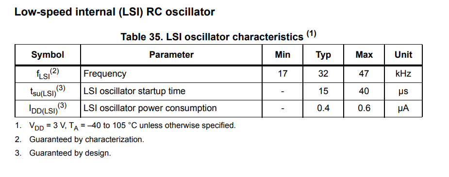
In other words, the LSI clock can run half as slow or 1.5 times as fast as expected.

±47% is equivalent to ±470 000 ppm whereas any normal crystal has a tolerance of ±20 ppm.

More recent STM32 families like the STM32H747XI have improved LSI accuracy:

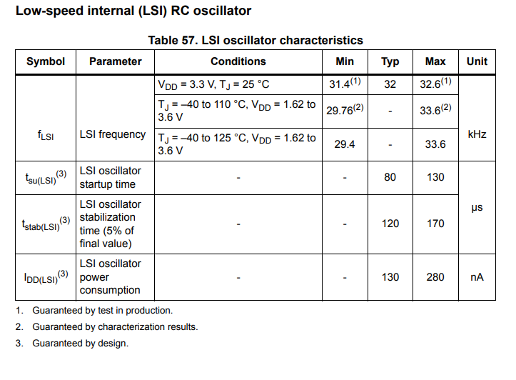
This amounts to a tolerance of ±1.875 % which is equivalent to ±18 750 ppm – still orders of magnitude more than any crystal or even ceramic resonator.

Can you tune out the difference by RTC digital tuning?

The STM32 digital tuning only has a range of -487.1 ppm to +488.5 ppm – but even for the much more accurate STM32H747XI, you would need a tuning range of at least ±20 000 ppm in order to compensate for initial inaccuracies and temperature coefficient.

What can you do to get better accuracy?

Typically, I recommend to just use a crystal for the RTC – or use an external RTC altogether.

Regarding the IWDG, you have no choice but to use the LSI. Typically you can just select a longer reset interval to avoid unintended watchdog resets if your LSI is running much faster than the standard 32 kHz, or you can just reset the watchdog more often. If you reset your watchdog in an interrupt, you should consider using a higher priority interrupt – and do global interrupt disables less frequently and try to avoid having periods where interrupts are disabled globally for a long time continously.


Posted by Uli Köhler in Electronics, STM32