Electronics

How to fix Arduino error: ‘size_t’ has not been declared

Problem:

In Arduino, you see an error message like

src/main.cpp:7:48: error: 'size_t' has not been declared
void MyFunction(size_t size);

Solution:

Include stddef.h where size_t is declared:

#include <stddef.h>

Add this line to the top of the file where the error occured.

Posted by Uli Köhler in Arduino, C/C++, Embedded, PlatformIO

How to fix Arduino I2C Wire error: call of overloaded ‘begin(const int&, const int&, int)’ is ambiguous

Problem:

You are trying to call Wire.begin() for I2C using

Wire.begin(Pin_I2C_SDA, Pin_I2C_SCL, 400000);

but you see an error message like

src/MyI2C.cpp: In function 'void MyInitI2C()':
src/NyI2C.cpp:139:47: error: call of overloaded 'begin(const int&, const int&, int)' is ambiguous
     Wire.begin(Pin_I2C_SDA,Pin_I2C_SCL, 400000);
                                               ^
In file included from include/MyIO.hpp:2:0,
                 from src/MyI2C.cpp:2:
/home/uli/.platformio/packages/framework-arduinoespressif32/libraries/Wire/src/Wire.h:79:10: note: candidate: bool TwoWire::begin(int, int, uint32_t)
     bool begin(int sda=-1, int scl=-1, uint32_t frequency=0); // returns true, if successful init of i2c bus
          ^
/home/uli/.platformio/packages/framework-arduinoespressif32/libraries/Wire/src/Wire.h:80:10: note: candidate: bool TwoWire::begin(uint8_t, int, int, uint32_t)
     bool begin(uint8_t slaveAddr, int sda=-1, int scl=-1, uint32_t frequency=0);

Solution:

This happens with specific versions of the Arduino framework. For me it happened specifically when upgrading to arduino-esp32 version 2.0.1.

You need to explicitly cast the third argument (400000) to uint32_t in order to tell the compiler which of the two functions you want to call:

Wire.begin(Pin_I2C_SDA, Pin_I2C_SCL, 400000);
Posted by Uli Köhler in Arduino, C/C++, Embedded, PlatformIO

How should a PoE flyback transformer look on the oscilloscope

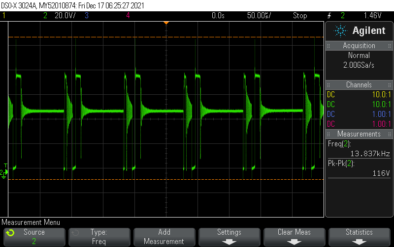
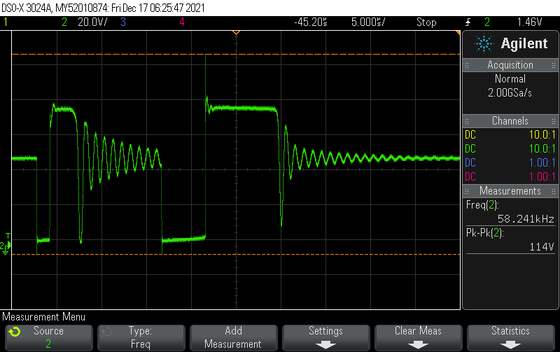
Measure at the pin not connected to the 48VDC line i.e. the pin of the transformer connected to the MOSFET / integrated flyback regulator IC (If unsure, try it out).

Depending on how exactly the IC works and the load (and the circuitry), these waveforms look quite differently. So the following pictures are mostly for basic reference.

Posted by Uli Köhler in Electronics, EMI, PoE

How to compute resistor voltage divider ratio using Python

Use UliEngineering to compute the ratio of the voltage divider:

from UliEngineering.Electronics.VoltageDivider import *

# This prints 0.9578544061302683
print(voltage_divider_ratio("2.2k", "50k"))
# In other words, the output voltage of a 2.2kOhm / 50kOhm voltage divider
# equals 0.9578544061302683 times the input voltage.

You can install UliEngineering using pip such as:

sudo pip3 install UliEngineering


Posted by Uli Köhler in Electronics, Python

How to initialize LittleFS in PlatformIO on the ESP32 using the lorol/LittleFS library

Note: I don’t recommend using the loros/LittleFS library when using an up-to-date version of the arduino-esp32 framework such as 2.0.5 – the newer versions of this framework come with an embedded LittleFS framework. See TODO for instructions how to initialize the library.

Currently you need to add the LittleFS-ESP32 library in platformio.ini (the library is available as part of the core arduino-espressif32 bleeding edge version but you need that library in the standard version):

lib_deps =
    lorol/LittleFS_esp32 @ ^1.0.6

Now include LittleFS:

#include <LITTLEFS.h>

#define SPIFFS LITTLEFS

Initialize it using

// Initialize LittleFS
if (!LITTLEFS.begin(false /* false: Do not format if mount failed */)) {
  Serial.println("Failed to mount LittleFS");
  if (!LITTLEFS.begin(true /* true: format */)) {
    Serial.println("Failed to format LittleFS");
  } else {
    Serial.println("LittleFS formatted successfully");
  }
} else { // Initial mount success
}


Posted by Uli Köhler in Arduino, Embedded, ESP8266/ESP32, PlatformIO

ArduinoJSON: How to fix 1 or 0 being printed instead of true/false

volatile bool value = true;

DynamicJsonDocument json(1024);
json["ok"] = value;
serializeJson(json, Serial);

This will print {"ok": 1} instead of {"ok": true} due to value being declared volatile (it works with just bool value, it does not work with volatile bool value).

In order to force {"ok": true}, just case value to bool:

json["ok"] = (bool)value;

Full example

volatile bool value = true;

DynamicJsonDocument json(1024);
json["ok"] = (bool)value;
serializeJson(json, Serial);


Posted by Uli Köhler in Arduino, Embedded, PlatformIO

FreeRTOS mutex minimal example

This is how you create and use a mutex in FreeRTOS:

Includes:

#include <freertos/semphr.h>


Global declaration

SemaphoreHandle_t myMutex;

Initialization code

Call this once, before using it:

myMutex = xSemaphoreCreateMutex();

How to lock & unlock the mutex

// Wait a maximum of 10ms to lock the mutex
if(xSemaphoreTake(myMutex, 10 / portTICK_PERIOD_MS) == pdTRUE) {
   // Success locking the mutex
   // TODO: Your code goes here!
   // Unlock the mutex!
   xSemaphoreGive(myMutex);
} else {
   // Failed to lock the mutex within timeout
   // DO NOT use the resource protected by the mutex
   // DO NOT unlock (xSemaphoreGive) !
}


Posted by Uli Köhler in Embedded, FreeRTOS, PlatformIO

ESPAsyncWebserver basic ArduinoJSON handler example

server.on("/api/test", HTTP_GET, [](AsyncWebServerRequest *request) {
      // Respond with JSON {"status": "ok"}
      AsyncResponseStream *response = request->beginResponseStream("application/json");
      DynamicJsonDocument json(1024);
      json["status"] = "ok";
      serializeJson(json, *response);
      request->send(response);
});


Posted by Uli Köhler in ESP8266/ESP32, Networking

ESPAsyncWebserver handler example with int query argument

This example is based on our basic example and shows how to use an int query parameter, e.g. http://192.168.1.112/api/test?param=2

server.on("/api/test", HTTP_GET, [](AsyncWebServerRequest *request) {
      int param = request->getParam("param")->value().toInt();
      // TODO: Do something with param!

      // Respond with JSON {"status": "ok"}
      AsyncResponseStream *response = request->beginResponseStream("application/json");
      DynamicJsonDocument json(1024);
      json["status"] = "ok";
      json["param"] = param;
      serializeJson(json, *response);
      request->send(response);
});


Posted by Uli Köhler in ESP8266/ESP32, Networking

How to print all preprocessor flags in PlatformIO

In order to show the values of all preprocessor flags, set this in platformio.ini:

build_flags = -E -dM

Now rebuild and you’ll see an error message like

Linking .pio/build/ESP32/firmware.elf
.pio/build/ESP32/src/main.cpp.o: file not recognized: File format not recognized
collect2: error: ld returned 1 exit status
*** [.pio/build/ESP32/firmware.elf] Error 1

This error is expected since GCC will not produce object files as output but preprocessor output definitions!

Now open the respective “object” files in your text editor:

code .pio/build/ESP32/src/main.cpp.o

where ESP32 is the name of your build configuration in platformio.ini. You will see all the definitions like this:

#define VSPI 3
#define XTENSA_HWCIDVERS_T1030_3 12
#define GPIO_PIN19_INT_TYPE 0x00000007
#define CONFIG_LWIP_MAX_RAW_PCBS 16
#define XTENSA_HWVERSION_RD_2012_4 240004
#define SPI_CLOCK_DIV32 0x013c1001
#define VALUE_GET_FIELD(_r,_f) (((_r) >> (_f ##_S)) & (_f))
#define GPIO_FUNC40_IN_INV_SEL (BIT(6))
#define GPIO_SIG31_IN_SEL (BIT(7))
#define ETS_RWBLE_NMI_SOURCE 9
#define RTC_IO_PDAC1_DAC_S 19
#define LWIP_HOOK_TCP_ISN lwip_hook_tcp_isn
#define RTC_IO_PDAC1_DAC_V 0xFF
#define XCHAL_INT30_TYPE XTHAL_INTTYPE_EXTERN_EDGE
#define _ETS_SET_INTLEVEL(intlevel) ({ unsigned __tmp; __asm__ __volatile__( "rsil   %0, " _ETSTR(intlevel) "\n" : "=a" (__tmp) : : "memory" ); })
#define B11101001 233
#define SPIWP_IN_IDX 4
#define MEMP_NUM_API_MSG MEMP_NUM_TCPIP_MSG_API
#define GPIO_FUNC74_IN_INV_SEL_M (BIT(6))
// ...


Posted by Uli Köhler in Electronics, Embedded, PlatformIO

How to add preprocessor build flags in PlatformIO

In order to define a preprocessor build flag in PlatformIO, add it to build_flags in platformio.ini, prefixing it with -D:

build_flags = -DQUICKSPI_DEBUG_WRITES

or, in order to define it to a specific value, use

build_flags = -DQUICKSPI_DEBUG_WRITES=1


Posted by Uli Köhler in C/C++, PlatformIO

What is the distribution of forward voltages within in a LED bin (binning by forward voltage)?

In our previous post What is the forward voltage deviation of typical power LEDs? we discussed that the typical forward voltage tolerance of LEDs. In this post we will discuss considerations regarding. Note that this is not based on actual distribution data since I could not find any, however it is based on actual datasheets and actual LEDs.

Since LEDs are binned, the following assumptions can be considered true if we assume what is promised in the datasheet is actually true:

  • Since each LED’s forward voltage is actually measured (this is the way the LEDs), no LED is outside the binning range
  • The LEDs are binned from an unknown base distribution of LEDs. Note that it is totally allowable to produce more LEDs in one bin than another, throw away some fraction of the LEDs or

First-level model: Truncated uniform distribution

As a first-level model, we can assume the LEDs to be uniformly distributed within the forward voltage range of the bin. In other words, for a bin of 2.90V to 3.0V (see the previous post), the likelihood of having a LED with Vf=2.91V is exactly the same as Vf=2.97V, but the likelihood of having a LED with Vf=2.88V is zero.

Second-level model: Unskewed non-uniform base distribution

Typical manufacturing distributions are not uniformly distributed but have some shape imposed by the process – such as a normal distribution. For simplicity, we can assume that the forward voltage distribution is an unskewed normal distribution centered around the average of the lowest and the highest possible forward voltage (lowest voltage of the lowest bin plus highest voltage of the highest bin, divided by 2).

In this second-level model, the bins lower than the center of the distribution will have a higher likelihood of having one of the higher voltages. For example, the 2.60V to 2.70V bin will have a slighly higher likelihood of drawing a Vf=2.69V LED than drawing a Vf=2.61V LED. For bins with voltages higher than the center of the distribution, the likelihood of drawing a lower voltage LED will be slightly higher. How large the difference in likelihoods is not only depends on the unknown base distribution, so we can’t assume all too much about it. But consider that the manufacturer will strictly avoid to throw away LEDs unneccessarily. So at least one of the following considerations must be true:

  • The LEDs thrown away due to forward voltage consideration are unmarketable
    • possibly because the number of LEDs produced outside the actual bins are too low to consider introducing another bin
    • possibly because these LEDs are considered defective or untestable (such as due to their light output not being within the specs)
  • Overall, the manufacturer will attempt to optimize the process in order to minimize the number of LEDs to throw away since they consume resources (manufacturing resources & time to test) but are thrown away
    • A sensible base assumption is that the number of LEDs sorted out is in the low single percent digits. Assume 2% with high variability between manufacturers if you lack better data.
  • The LEDs which are sorted out are marketed under a secondary (“non-premium”) brand with higher tolerances on at least some of the parameters

Third-level model: Considering tolerances and rounding modes

What does it mean to have a LED with a forward voltage of 2.70V – does an actual forward voltage 2.701V  put the LED into Bin A from 2.60V to 2.70V or Bin B from 2.70V to 2.80V? If we consider the measurement to be 100% accurate, obviously it will be put into Bin B.

However, even the OSRAM datasheet from our previous post lists

The Forward voltage is measured during a current pulse duration of typically 1 ms with a tolerance of ± 0.05V .

Note that ±50mV is quite a significant tolerance. Since we don’t know what the actual deviation of the measurement equipment is, we need to consider a tolerance of ±50mVfor the bin voltages. For example, Bin B could have LEDs with a Vf from 2.65V to 2.85V. Instead of the deviation of ±1.8% (from 2.70V to 2.80V, referred to their center Vf),  this process results in a deviation of ±2.65% – approximately double the tolerance we have seen in our previous model.

Typically, the errors in such measurement are driven mostly by offsets than by noise (we’re talking about measurements in the low tens of millivolts here, you don’t need metrology-grade equipment to do that). Calibrating equipment all the time costs lots of money, hence defining even slighly higher tolerances saves a lot of money. If you were to guarantee a higher tolerance, you would need to account for a stricter temperature control during the binning process due to the temperature coefficient of Vf, with single-degree, and you would have to calibrate and adjust your equipment much more often.

If we were to assume that only a single testing device tested our equipment, the unknown offset would slightly move the truncated voltage distribution, but not more than the 50mV specified devation (depends on the manufacturer of course and is not always found in datasheets) in either direction. In other words, Bin B with a nominal 2.70V to 2.80V could be 2.66V to 2.76V with no LED outside that range. That range, however, is unknown

Further considerations

However we still need to consider that most LEDs (except some very expensive ones of course) are ultra-high-quantity, low-cost products produced in vast quantities. You can only speed up0 a production machine up to a certain point economically – beyond that point, it’s much better to just place multiple machines performing the same manufacturing step next to one another. While this certainly can’t be guaranteed, it can not be assumed that all LEDs from a single part number are produced by the same machine. Hence, we can’t assume that the offset is constant within a single bin. One binning machine might have an offset of +0.03V while the next one might have an offset of -0.04V.

However, there is some basis for an argument that whatever is sold on a single reel could be from a single binning machine – in other words, buy a continous reel or tape of LEDs from someone you trust to give you a virgin reel and not a mix of separate reels connected together, and you have a higher likelihood of the actual voltages being more like ±1.8% than ±2.65% since it has been tested. But still, if it is not guaranteed explicitly, you have no guarantee that LED bins from different machines are not thrown together into a single, physical, bin. Since most quality manufacturers try to implement some form of traceability system to track back errors appearing in the field to whatever process or machine caused them, it is more likely than not that continous tapes have slighly less Vf deviation that just LEDs of the same part number.

Even within a single reel, you could see adjacent LEDs have slightly less deviation than if you compare LEDs from one end of the reel to the other end – say, because the temperature during the binning process varied very very slightly, affecting the measured Vf by means of the the Vf temperature coefficient.

One aspect we did not consider so far is outliers. Many quality manufacturing processes are designed with five-sigma tolerance in mind (i.e. at most one in every 3.5 million LEDs will not adhere to specifications). This means that even though the manufacturing & binning process effectively does 100% testing of the LEDs, at least every once in a while you will produce an outlier – be it every 1 million, every 10 million or every trillion parts. In practice, reaching five sigma is hard and causes for rare errors are literally everywhere. So even if the probability of a Bin having an LED with a voltage outside the specified Vf range is extremely low, say, 0.00002%, it is not zero. Note that even an LED only a millivolt outside the specification would technically considered an outlier, and most outliers are only just outliers – even within outliers, only a small fraction is way outside the tolerance. Except for one group: Actually defective LEDs.

Consider this scenario: What if the wirebond has an intermittent contact for some reason, and during testing it works. This will produce an outlier that may even work for a couple of years after being assembled on a PCB. But when the LED is temperature-cycled over and over again by normal operation, it might fail at some point – or it might not. The point to take home here is that not only is life influenced by statistics, life itself is statistics. So you should consider guarantees as someone has reason to believe some event is extremely unlikely, but you will never reach 0% or 100%.
Posted by Uli Köhler in Electronics

What is the forward voltage deviation of typical power LEDs?

A typical starting point is to assume a Vf deviation of ±10% to ±15%, but you typically buy LEDs binned by their measured forward voltage.

As an example, we’ll use the OSRAM 3W OSCONIQ® P 3737 as an example: The datasheet lists the forward voltage range as 2.60V to 3.10V with a nominal of 2.75V – in other words, -5.5%, +12.7%. Since you buy LEDs binned by forward voltage, the actual deviation is much lower within a single part number. For example, the voltage range in the L2 bin is ±1.7%

Note that this does not take into account the forward voltage change due to the Vf temperature coefficient (the temperature coefficient will be very slightly different for each individual LED, but this doesn’t matter too much in practice – so you can mostly assume that the forward voltage temperature coefficient is constant).

Posted by Uli Köhler in Electronics

How to install LXI-Tools with lxi-gui on Ubuntu

The easiest way of getting lxi-tools and lxi-gui running under Ubuntu is to install it using snap:

sudo snap install lxi-tools

After that, just run it using

lxi-gui

or the command line tool

lxi


Posted by Uli Köhler in Electronics

Diagnosing I2C issues using an oscilloscope: Slow rising edge, fast falling edge

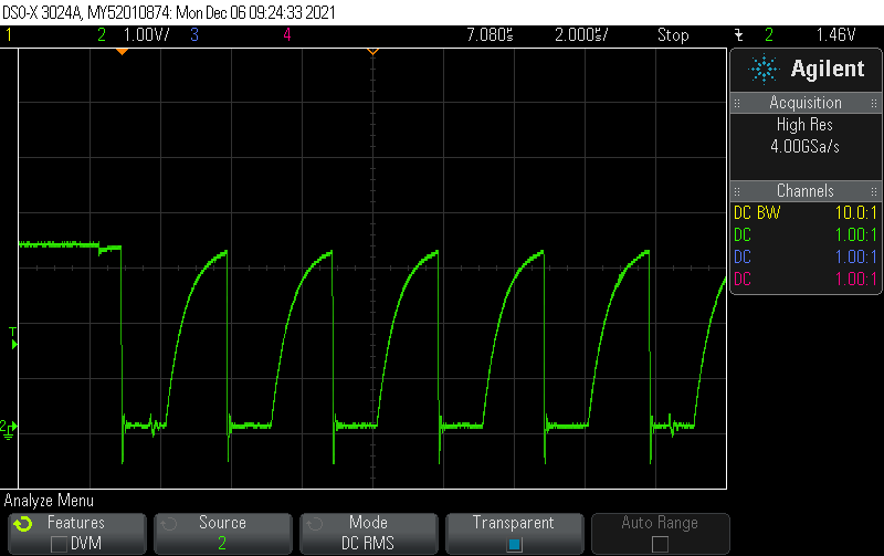
If your I2C clock and/or data signal look like this:

in other words, if the rising edge is very slow and not sharp compared to the you are facing an issue with a pull-up resistor which is too large. A good point to start is to use a pull-up resistor 1/4 the value of the pull-up currently installed on your board. If you don’t have any pull-up on your board, start with a 2.2 kOhm pull-up resistor.

As a hotfix, you can operate I2C at slower speed like 100 kHz or even slower (like 10 kHz). This will temporarily fix the issue and depending on your application there might not be any need to go faster than that.

Posted by Uli Köhler in Compliance, Electronics, Embedded

How should the SPI SCLK look on the oscilloscope?

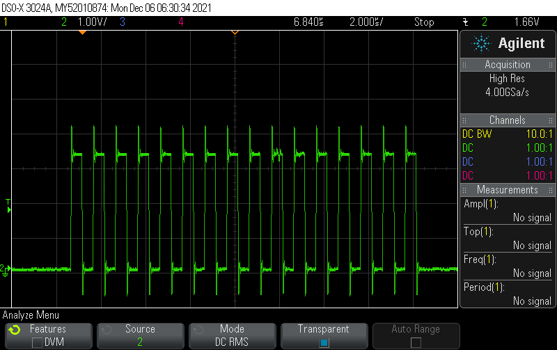
SPI is typically used at 1-20MHz clock frequency. Start with setting the oscilloscope to 2 microseconds per division and 2V per division. Hence, set your scope. Set the trigger to edge mode to trigger at half the supply voltage (e.g. 1.65V for 3.3V supply voltage).The following example is SPI running at 1 MHz on a supply of 3.3V:

Always start by measuring SCLK, to verify both a valid signal clock and your measurement setup. The signal should always look like this:

The first aspect to verify here is that the SCLK should be mostly symmetric (50% duty cycle) and running continously throughout each SPI data transfer. The frequency should typically not change during a single SPI transfer.

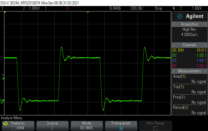
SPI tolerates a significant amount of overshoot. In case you have signal integrity issues, you can typically just reduce the clock speed. In order to have a closer look on the signal integrity aspects, zoom in so you see just one clock cycle.


The amount of overshoot you see in our example is totally fine. What you should look for here is that both the rising and falling edge should be reasonably sharp and the 0 and 1 bits should be clearly visible.

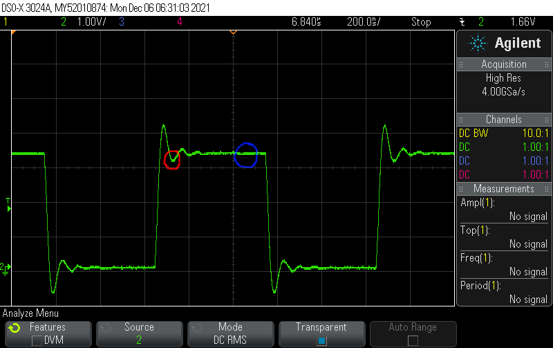
Regarding overshoot/undershoot, a good rule of thumb is that during the 1 bit, the voltage should never be less than 0.8 times the steady-state voltage during the one bit (see below for red and blue markers):

Similarly, during the 0 bit, the voltage should never be less than 0.2 times the steady-state voltage during the one bit

Note that not only does your PCB affect the signal integrity – your measurement setup (oscilloscope & probe) affects them to some extent as well.

Posted by Uli Köhler in Compliance, Electronics, Embedded

What is the FreeRTOS equivalent to Arduino’s delay()?

Instead of Arduino’s

delay(5); // delay for five milliseconds

use this in FreeRTOS:

vTaskDelay(5 / portTICK_PERIOD_MS);
Posted by Uli Köhler in Arduino, Electronics, Embedded, FreeRTOS

How to add FreeRTOS task (“thread”) to any PlatformIO project

Most PlatformIO default configurations already have FreeRTOS enabled – they just don’t use it.

In order to start a new FreeRTOS “thread” (called task in FreeRTOS-speak), first add these includes:

#include <freertos/FreeRTOS.h>
#include <freertos/task.h>

Now add the task function and handle:

TaskHandle_t myTaskHandle;
void MyTask( void * parameter )
{
    for(;;)
    {
       // TODO Task code goes here
    }
    // if you ever exit the loop, this is here to clean up the resources
    vTaskDelete( NULL );
}

then start the task using this code once, for example in your main function:

// Start MyTask thread
xTaskCreate(
    MyTask, // Task function
    "MyTask", // Name
    10000, // Stack size
    NULL, // Parameter
    1, // Priority
    &myTaskHandle);

Also see our new post on how to use xTaskCreateStatic() to use statically allocated instead of dynamically allocated stack memory for the task: FreeRTOS task with static stack memory (xTaskCreateStatic) example

Posted by Uli Köhler in C/C++, Electronics, Embedded, FreeRTOS, PlatformIO

How to add library dependency from local filesystem in PlatformIO

If you want to add a library dependency to lib_deps where the library is from the local file system, just add the full path to lib_deps

lib_deps =
    /home/user/MyCustomLib

This is really handy when developing libs since it allows you to just save changes in the source code and rebuild your main project without any need to publish and update the package first.

Note that you need to Clean and then Build or Upload in order to update the files from the local directory. PlatformIO will cache them unless you Clean and then rebuild!

Posted by Uli Köhler in PlatformIO