Electronics

What does the ~ (tilde) mean for pins like “~RESET”?

The ~ in pins names like ~RST means not.

  • A pin named without ~, for example RST or RESET, will perform its function (e.g. reset the device) when it is connected to VCC
  • A pin named with ~, for example ~RST or ~RESET, will perform its function (e.g. reset the device) when it is connected to GND

~RESET has exactly the same meaning as overlining the name – for example \overline{\text{RESET}}. Some manufacturers also use use n instead of ~RESET or \overline{\text{RESET}}

Posted by Uli Köhler in Electronics

What does the “n” mean for pins like “nRST”?

The n in pins names like nRST means not.

  • A pin named without n, for example RST or RESET, will perform its function (e.g. reset the device) when it is connected to VCC
  • A pin named with n, for example nRST or nRESET, will perform its function (e.g. reset the device) when it is connected to GND

nRESET has exactly the same meaning as overlining the name. For example \overline{\text{RESET}}. Some manufacturers prefer to use n instead of \overline{\text{RESET}} or ~RESET

Posted by Uli Köhler in Electronics

SN74LV245A as level shifter: How to use the ~OE pin

The ~OE pin on the SN74LV245A defines whether to enable the outputs on the chip. Which pins are inputs and which are outputs is defined by the DIR pins, see SN74LV245A as level shifter: How to use DIR pin for more information.

  • If ~OE is low (i.e. connected to GND), all output pins are enabled
  • If ~OE is high (i.e. connected to Vcc), all output pins are disabled

Note that there is no way to disable individual output pins for the SN74LV245A. You can only enable or disable all the pins together.

In most applications as a level shifter, you want to always enable the output: In order to do that, connect the ~OE pin to GND.

Posted by Uli Köhler in Electronics, Embedded

SN74LV245A as level shifter: How to use the DIR pin

The DIR pin on the SN74LV245A defines whether the A pins or the B pins are the input pins.

  • If DIR is low (i.e. connected to GND), all B pins are inputs and all A pins are outputs.
  • If DIR is high (i.e. connected to Vcc), all A pins are inputs and all B pins are outputs.
Posted by Uli Köhler in Electronics, Embedded

How to setup Home-Assistant MQTT with username & password

The following setting in configuration.yml connects to a local mosquitto MQTT broker using username and password:

mqtt:
  broker: "127.0.0.1"
  username: "homeassistant"
  password: "iraughij3Phoh7ne9Aoxingi2eimoo"

Complete configuration.yml:

default_config:

http:
  use_x_forwarded_for: true
  trusted_proxies:
  - 127.0.0.1
  ip_ban_enabled: true
  login_attempts_threshold: 5

mqtt:
  broker: "127.0.0.1"
  username: "homeassistant"
  password: "iraughij3Phoh7ne9Aoxingi2eimoo"

# Text to speech
tts:
  - platform: google_translate

group: !include groups.yaml
automation: !include automations.yaml
script: !include scripts.yaml
scene: !include scenes.yaml


Posted by Uli Köhler in Home-Assistant, MQTT

How to fix Home-Assistant A request from a reverse proxy was received from 127.0.0.1, but your HTTP integration is not set-up for reverse proxies

Problem:

When running home-assistant (using docker or other methods) behind a reverse proxy such as nginx, you see 400: Bad request response codes and the following error message appears in the HomeAssistant logs:

homeassistant    | 2021-11-25 03:03:59 ERROR (MainThread) [homeassistant.components.http.forwarded] A request from a reverse proxy was received from 127.0.0.1, but your HTTP integration is not set-up for reverse proxies

Solution:

Edit config/configuration.yaml and add:

http:
  use_x_forwarded_for: true
  trusted_proxies:
  - 127.0.0.1
  ip_ban_enabled: true
  login_attempts_threshold: 5

just below the default_config: line, adding a newline in between.   If your reverse proxy is running on another host, replace 127.0.0.1 by the IP address of that host.

Complete configuration.yml example:

# Configure a default setup of Home Assistant (frontend, api, etc)
default_config:

http:
  use_x_forwarded_for: true
  trusted_proxies:
  - 127.0.0.1
  ip_ban_enabled: true
  login_attempts_threshold: 5

# Text to speech
tts:
  - platform: google_translate

group: !include groups.yaml
automation: !include automations.yaml
script: !include scripts.yaml
scene: !include scenes.yaml

Now restart home-assistant and your reverse proxy should work fine.

Posted by Uli Köhler in Home-Assistant

How to fix Docker Home-Assistant [finish] process exit code 256

Problem:

Your Docker container running home-assistant always exits immediately after starting up, with the log being similar to this:

$ docker-compose up
Recreating homeassistant ... done
Attaching to homeassistant
homeassistant    | [s6-init] making user provided files available at /var/run/s6/etc...exited 0.
homeassistant    | [s6-init] ensuring user provided files have correct perms...exited 0.
homeassistant    | [fix-attrs.d] applying ownership & permissions fixes...
homeassistant    | [fix-attrs.d] done.
homeassistant    | [cont-init.d] executing container initialization scripts...
homeassistant    | [cont-init.d] done.
homeassistant    | [services.d] starting services
homeassistant    | [services.d] done.
homeassistant    | [finish] process exit code 256
homeassistant    | [finish] process received signal 15
homeassistant    | [cont-finish.d] executing container finish scripts...
homeassistant    | [cont-finish.d] done.
homeassistant    | [s6-finish] waiting for services.
homeassistant    | [s6-finish] sending all processes the TERM signal.
homeassistant    | [s6-finish] sending all processes the KILL signal and exiting.
homeassistant exited with code 0

Solution:

You need to start the container with --privileged=true if using docker directly to start up the service, or use privileged: true if using docker-compose.

Here’s an example of a working docker-compose.yml file:

version: '3.5'
services:
  homeassistant:
    container_name: homeassistant
    restart: unless-stopped
    image: ghcr.io/home-assistant/home-assistant:stable
    network_mode: host
    privileged: true
    environment:
      - TZ=Europe/Berlin
    volumes:
      - ./config:/config

https://techoverflow.net/wp-admin/post-new.php#category-all

Posted by Uli Köhler in Container, Docker, Home-Assistant

How I fixed tuya-convert Nous A1 SmartConfig complete. Resending SmartConfig Packets loop

Problem:

While trying to flash a device using tuya-convert, you see an error message like

======================================================
Starting smart config pairing procedure
Waiting for the device to install the intermediate firmware
Put device in EZ config mode (blinking fast)
Sending SSID                  vtrust-flash
Sending wifiPassword          
Sending token                 00000000
Sending secret                0101
................
SmartConfig complete.
Resending SmartConfig Packets
.................
SmartConfig complete.
Resending SmartConfig Packets
.................
SmartConfig complete.
Resending SmartConfig Packets
................
SmartConfig complete.
Resending SmartConfig Packets
.................
SmartConfig complete.
Resending SmartConfig Packets
.................
SmartConfig complete.
Resending SmartConfig Packets
................
SmartConfig complete.
Resending SmartConfig Packets
.................
SmartConfig complete.
Resending SmartConfig Packets
.................
SmartConfig complete.
Resending SmartConfig Packets
................
SmartConfig complete.
Resending SmartConfig Packets
..............
Timed out while waiting for the device to (re)connect

and the flash procedure fails.

Solution:

You can see the actual error log in scripts/smarthack-psk.log. In my case the error was the one described in our previous post How I fixed tuya-convert Nous A1 could not establish sslpsk socket: [SSL: NO_SHARED_CIPHER] no shared cipher

The current version of ./install_reqs.sh does not install the sslpsk module correctly (the error message is somewhat hidden at the top of the log). Install it manually using

sudo -H python3 -m pip install --upgrade sslpsk


Posted by Uli Köhler in Electronics, Embedded

How I fixed tuya-convert Nous A1 could not establish sslpsk socket: [SSL: NO_SHARED_CIPHER] no shared cipher

Problem:

While trying to flash a device using tuya-convert, you see an error message like

Traceback (most recent call last):
  File "/home/pi/tuya-convert/scripts/./psk-frontend.py", line 6, in <module>
    import sslpsk
ModuleNotFoundError: No module named 'sslpsk'
Traceback (most recent call last):
  File "/home/pi/tuya-convert/scripts/./psk-frontend.py", line 6, in <module>
    import sslpsk
ModuleNotFoundError: No module named 'sslpsk'
new client on port 443 from 10.42.42.10:49144
could not establish sslpsk socket: [SSL: NO_SHARED_CIPHER] no shared cipher (_ssl.c:1123)
don't panic this is probably just your phone!
new client on port 443 from 10.42.42.10:49150
could not establish sslpsk socket: [SSL: NO_SHARED_CIPHER] no shared cipher (_ssl.c:1123)
don't panic this is probably just your phone!
new client on port 443 from 10.42.42.10:49154
could not establish sslpsk socket: [SSL: NO_SHARED_CIPHER] no shared cipher (_ssl.c:1123)
don't panic this is probably just your phone!
new client on port 443 from 10.42.42.10:49156
could not establish sslpsk socket: [SSL: NO_SHARED_CIPHER] no shared cipher (_ssl.c:1123)
don't panic this is probably just your phone!
new client on port 443 from 10.42.42.10:49160
could not establish sslpsk socket: [SSL: NO_SHARED_CIPHER] no shared cipher (_ssl.c:1123)
don't panic this is probably just your phone!
new client on port 443 from 10.42.42.10:49162
could not establish sslpsk socket: [SSL: NO_SHARED_CIPHER] no shared cipher (_ssl.c:1123)
don't panic this is probably just your phone!
new client on port 443 from 10.42.42.10:49164
could not establish sslpsk socket: [SSL: NO_SHARED_CIPHER] no shared cipher (_ssl.c:1123)
don't panic this is probably just your phone!
new client on port 443 from 10.42.42.10:49172
could not establish sslpsk socket: [SSL: NO_SHARED_CIPHER] no shared cipher (_ssl.c:1123)
don't panic this is probably just your phone!
new client on port 443 from 10.42.42.10:49174
could not establish sslpsk socket: [SSL: NO_SHARED_CIPHER] no shared cipher (_ssl.c:1123)
don't panic this is probably just your phone!
new client on port 443 from 10.42.42.10:49176
could not establish sslpsk socket: [SSL: NO_SHARED_CIPHER] no shared cipher (_ssl.c:1123)
don't panic this is probably just your phone!
new client on port 443 from 10.42.42.10:49178
could not establish sslpsk socket: EOF occurred in violation of protocol (_ssl.c:1123)
Traceback (most recent call last):
  File "/home/pi/tuya-convert/scripts/./psk-frontend.py", line 61, in new_client
    ssl_sock = sslpsk.wrap_socket(s1,
  File "/usr/local/lib/python3.9/dist-packages/sslpsk/sslpsk.py", line 110, in wrap_socket
    sock.do_handshake()
  File "/usr/lib/python3.9/ssl.py", line 1309, in do_handshake
    self._sslobj.do_handshake()
ssl.SSLEOFError: EOF occurred in violation of protocol (_ssl.c:1123)

During handling of the above exception, another exception occurred:

Traceback (most recent call last):
  File "/home/pi/tuya-convert/scripts/./psk-frontend.py", line 113, in <module>
    main()
  File "/home/pi/tuya-convert/scripts/./psk-frontend.py", line 109, in main
    p.data_ready_cb(s)
  File "/home/pi/tuya-convert/scripts/./psk-frontend.py", line 80, in data_ready_cb
    self.new_client(_s)
  File "/home/pi/tuya-convert/scripts/./psk-frontend.py", line 72, in new_client
    if "NO_SHARED_CIPHER" in e.reason or "WRONG_VERSION_NUMBER" in e.reason or "WRONG_SSL_VERSION" in e.reason:
TypeError: argument of type 'NoneType' is not iterable

and the flash procedure fails.

Solution:

The current version of ./install_reqs.sh does not install the sslpsk module correctly (the error message is somewhat hidden at the top of the log). Install it manually using

sudo -H python3 -m pip install --upgrade sslpsk


Posted by Uli Köhler in Electronics, Embedded

How to fix tuya-convert ModuleNotFoundError: No module named ‘Cryptodome’

Problem:

While trying to flash a device using tuya-convert, you see an error message like

======================================================
Starting smart config pairing procedure
Waiting for the device to install the intermediate firmware
Traceback (most recent call last):
  File "/home/pi/tuya-convert/scripts/./smartconfig/main.py", line 15, in <module>
    from smartconfig import smartconfig
  File "/home/pi/tuya-convert/scripts/smartconfig/smartconfig.py", line 43, in <module>
    from multicast import multicast_head, encode_multicast_body
  File "/home/pi/tuya-convert/scripts/smartconfig/multicast.py", line 12, in <module>
    from Cryptodome.Cipher import AES
ModuleNotFoundError: No module named 'Cryptodome'
.........................................

and the flash procedure fails.

Solution:

The current version of ./install_reqs.sh does not install the pycryptodome module. Install it manually using

sudo -H python3 -m pip install --upgrade pycryptodome


Posted by Uli Köhler in Electronics, Embedded

How to pass firewall using PlatformIO espota ArduinOTA upload

ArduinoOTA’s protocol tries to connect to the host which is trying to program the device on a randomly chosen port. This often leads to the packets being filtered in a firewall since no rule exists to pass the packet and they are not related to an existing connection.

You could create a firewall rule to pass all traffic from the ESP8266/ESP32 to the programming host, but that is extremely insecure since it allows a hacked IoT device to hack your devices.

In order to fix it, add a fixed host port in platformio.ini using

upload_flags = --host_port=55910

and add these firewall rules:

allow from <programming host> to <IoT device> port 55910 TCP
allow from <IoT device> to <programming host> port 55190 TCP

Complete platformio.ini example:

[env:d1_mini_ota]
extends = env:d1_mini
upload_protocol = espota
upload_port = 192.168.178.25
upload_flags = --host_port=55910


Posted by Uli Köhler in Embedded, ESP8266/ESP32, PlatformIO

How to use FlexPWM NanoEdge Placer on the Teensy 4

You can not use the NanoEdge placer block on the Teensy 4.0 / Teensy 4.1 because the NanoEdge placer hardware unit is not built into the i.MX RT1062 processor the Teensy uses.

Source: Teensy Forums

Posted by Uli Köhler in Electronics, Teensy

How to use ESP32 as USB-to-UART converter in PlatformIO

The ESP32 can easily be used as USB-to-UART converter. Note that the ESP32 does not feature an USB interface by itself and ESP32 boards with an onboard USB connector just use an USB-to-UART converter (this is a separate chip on the board). Hence, from the ESP32 perspective, it

You can map UART TX and RX to any GPIO pin on the ESP32. While there are very, very slight performance advantages to using a set of predefined pins, this does not really matter in practice. In this example, we will use pin GPIO2 for UART RX and pin GPIO4 for UART TX.

Basically, the code is just copying bytes between Serial2 and Serial (connected to USB):

// Copy bytes incoming via PC serial
while (Serial.available() > 0) {
  Serial2.write(Serial.read());
}
// Copy bytes incoming via UART serial
while (Serial2.available() > 0) {
  Serial.write(Serial2.read());
}

Full example

#include <Arduino.h>

#define UART_RX_PIN 2 // GPIO2
#define UART_TX_PIN 4 // GPIO4

void setup() {
  // Serial connects to the computer
  Serial.begin(115200);
  // Serial2 is the hardware UART port that connects to external circuitry
  Serial2.begin(115200, SERIAL_8N1,
                UART_RX_PIN,
                UART_TX_PIN);
}

void loop() {
  // Copy byte incoming via PC serial
  while (Serial.available() > 0) {
    Serial2.write(Serial.read());
  }
  // Copy bytes incoming via UART serial
  while (Serial2.available() > 0) {
    Serial.write(Serial2.read());
  }
}

Regarding platformio.ini, we just need to set the monitor_speed to match the value in Serial.begin(115200);:

[env:nodemcu-32s]
platform = espressif32
board = nodemcu-32s
framework = arduino
monitor_speed = 115200


Posted by Uli Köhler in C/C++, Electronics, ESP8266/ESP32, PlatformIO

ESPAsyncWebserver: How to run code in main loop thread

When working with ESPAsyncWebserver, you will soon encounter one of its most fundamental limitations: Its code will always run in interrupts, hence you can’t use delay() or any function that uses delay() or similar functions internally.

However, there’s a simple programming pattern that will enable you to execute code in the main thread if requested by the webserver. Note: In this example, we will only cover how to activate code in the main loop from the webserver, but the response will be sent before the code in the main loop is run – hence, the response is just {"status": "ok"} and it doesn’t depend on whatever is happening on the main loop.

The idea is to have a global flag:

bool request_serial_output = false;

which is set in the webserver handler code, whereas the main loop checks the flag repeatedly:

void loop() {
  if(request_serial_output) {
    request_serial_output = false; // Clear flag
    // TODO Add handling code here
  }
}

Full example

This example uses PlatformIO and should work on any ESP32 board.

#include <Arduino.h>
#include <WiFi.h>
#include <ESPAsyncWebServer.h>
#include <ArduinoJson.h>

AsyncWebServer server(80);

bool request_serial_output = false;

void setup() { 
  Serial.begin(115200);
  // Connect Wifi, restart if not connecting
  // https://techoverflow.net/2021/01/21/how-to-fix-esp32-not-connecting-to-the-wifi-network/
  WiFi.begin("MyWifi", "mywifipassword");
  uint32_t notConnectedCounter = 0;
  while (WiFi.status() != WL_CONNECTED) {
      delay(100);
      Serial.println("Wifi connecting...");
      notConnectedCounter++;
      if(notConnectedCounter > 50) { // Reset board if not connected after 5s
          Serial.println("Resetting due to Wifi not connecting...");
          ESP.restart();
      }
  }
  Serial.print("Wifi connected, IP address: ");
  Serial.println(WiFi.localIP());

  // Initialize webserver URLs
  server.on("/api/test", HTTP_GET, [](AsyncWebServerRequest *request) {
      // Send request to main loop
      request_serial_output = true;
      // Send JSON "ok" response.
      // NOTE: The response will be sent BEFORE the main loop has finished
      // processing the request
      AsyncResponseStream *response = request->beginResponseStream("application/json");
      DynamicJsonDocument json(1024);
      json["status"] = "ok";
      serializeJson(json, *response);
      request->send(response);
  });

  // Start webserver
  server.begin();
}

void loop() {
  if(request_serial_output) {
    request_serial_output = false; // Clear flag
    // Output serial
    Serial.println("First message. Now waiting one second...");
    // Wait 1s. You can't do that in the webserver handler!
    delay(1000);
    // Output another message on Serial
    Serial.println("Second message!");
  }
}
[env:nodemcu-32s]
platform = espressif32
board = nodemcu-32s
framework = arduino
monitor_speed = 115200
lib_deps =
    ESP Async [email protected]
    [email protected]


Posted by Uli Köhler in ESP8266/ESP32, PlatformIO

How to enter serial bootloader on the ESP32

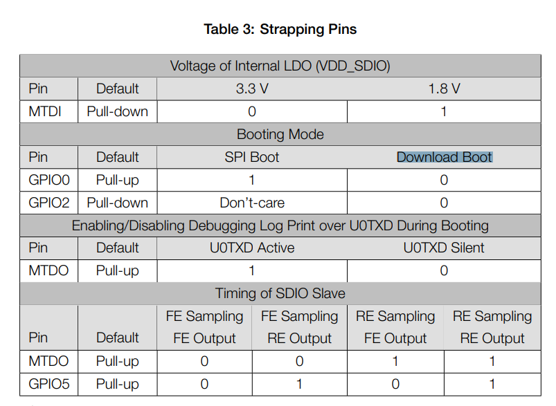
In order to enter the serial bootloader on the ESP32, connect both GPIO0 and GPIO2 to GND while the ESP32 is starting up.

A typical hardware sequence to enter the bootloader is:

  1. Connect GPIO0 and GPIO2 to GND
  2. Connect the EN or RST pin to GND for at least 100ms, then connect to 3.3V

The second step will restart the ESP32.

Posted by Uli Köhler in ESP8266/ESP32

What is “Download Mode” on the ESP32?

The ESP-WROOM-32E datasheet Table 3 defines that when GPIO0 and GPIO2 are low during startup, you will enter Download mode without Download mode being defined anywhere in the datasheet:

Download mode is the factory-integrated ROM serial bootloader. By strapping GPIO0 and GPIO2 low at the same time, you can flash a new firmware using the serial port.


Posted by Uli Köhler in Embedded, ESP8266/ESP32

How to check a stepper motor for open/short circuit?

In order to correctly check a stepper motor for a hard short circuit, you need an LCR meter. If you only have an multimeter, skip the winding inductance check.

Measuring the phase resistance

First, check the resistance of each phase winding (pair A and pair B). The resistance should be between 0.5 Ω and 5 Ω, but note that it is also influenced by your multimeter probes and the contact resistance from the probe to the pin. If possible, compare the measurement to the datasheet of your stepper motor or to the datasheet of your motor or a good motor of the same model. If the datasheet lists 1.5 Ω, I would accept anything from 1.0 Ω to 2.0 Ω. If you see an infinite resistance (typically indicated by OL [overload] on your multimeter), either you measured the wrong pins or your probes do not electrically contact the pins – or your motor has an open winding (no contact). Re-measure multiple time, trying to contact the pin on different points on the surface to confirm. Also check if your multimeter displays a sensible value if you short the multimeter probes.
If you see a resistance that is way too low (e.g. 0.2 Ω for a nominal 1.5 Ω motor), your winding is shorted. This is typically not caused by a bad contact from the probes to the pin, but re-measure a few times just to confirm.

Now measure the resistance from one of the phase A pins to one of the phase B pins. The resistance should typically be OL (overload – i.e. a resistance so high the multimeter can’t measure it), but at least 5.0 MΩ. If it is any less, this indicates that the phases are shorted to each other. Be sure that you measured the correct pins.

Measuring the phase inductance

Now, Check the inductance of each phase winding (pair A and pair B). The inductance should be a couple of mH, but never below 100uH. A lower inductance indicates an winding that is shorted internally. If possible, compare with the datasheet of your stepper motor or see What phase inductivity value should my stepper motor have? for more details on this topic.

Now check, using the resistance mode of your LCR meter, check if any phase wiring has. Typically the resistance between one phase winding and the other

If you don’t know which pins of the connector belong to which phase winding, the two pins of each pair should have an inductance that is within ±30% of each another at maximum.

Posted by Uli Köhler in 3D printing, Electronics

How to fix Marlin random driver error detected coil short circuit crash (Trinamic TMC)

Problem:

When using Trinamic drivers with the Marlin 3D printer firmware, you might occasionally experience errors like

Send: N4193 G1 X12.345 Y34.567 E122.15252
Recv: 
Recv: E driver error detected: 0x10136000
Recv: coil short circuit
Recv: 		X	Y	Z	E
Recv: Enabled		true	true	true	true
Recv: Set current	2000	2000	2000	1000
Recv: RMS current	1999	1999	1999	990
Recv: MAX current	2819	2819	2819	1396
Recv: Run current	31/31	31/31	31/31	19/31
Recv: Hold current	15/31	15/31	15/31	9/31
Recv: Global scaler	167/256	167/256	167/256	133/256
Recv: CS actual	31/31	31/31	22/31	19/31
Recv: PWM scale	196716	33095745	65576	33488924
Recv: vsense
Recv: stealthChop	true	true	true	true
Recv: msteps		128	128	128	128
Recv: interp		true	true	true	true
Recv: tstep		171	678	max	1580
Recv: PWM thresh.	24	24	411	13
Recv: [mm/s]		102	102	3	41
Recv: OT prewarn	false	false	false	false
Recv: triggered
Recv:  OTP		false	false	false	false
Recv: off time	4	4	4	4
Recv: blank time	24	24	24	24
Recv: hysteresis
Recv:  -end		2	2	2	2
Recv:  -start		1	1	1	1
Recv: Stallguard thrs	0	0	0	0
Recv: uStep count	62	32	227	497
Recv: DRVSTATUS	X	Y	Z	E
Recv: sg_result	0	0	395	0
Recv: stallguard
Recv: fsactive
Recv: stst		*	*		*
Recv: olb
Recv: ola
Recv: s2gb					*
Recv: s2ga
Recv: otpw
Recv: ot
Recv: Driver registers:
Recv: 		X	0x00:1F:40:00
Recv: 		Y	0x00:1F:40:00
Recv: 		Z	0x80:16:41:8B
Recv: 		E	0x10:13:60:00
Recv: 
Recv: 
Recv: echo:Driver error
Recv: Error:Printer halted. kill() called!
Changing monitoring state from "Printing" to "Error"

Solution:

If the error always occurs at the start of each print, be sure to check your stepper motor setup for actual shorts! Measure the inducitivity using an LCR meter to be sure, it should be around the rated value for your motor! See this post for information about typical stepper motor inductivity.

If the error occurs occasionally, it is recommended in the datasheet that you use more conservative short detection settings.

You need to make the change this in Marlin/src/module/stepper/trinamic.cpp.

Go to the section for the driver type you are using. In my example, this would be

#if HAS_DRIVER(TMC5160)
// ...
void tmc_init(/* ... */) {
   // NOTE: tmc_init() is the function we need to insert code in!
}
#endif

Now insert, just before the TERN(HYBRID_THRESHOLD, /* ... */) line (if such a line does not exist, insert at the end of the function:

// Set more conservative short detection settings
st.shortfilter(3); // 3us SHORT filter
st.s2vs_level(15); // Lowest sensitivity short to supply voltage protection
st.s2g_level(15); // Lowest sensitivity short to ground protection
st.shortdelay(1); // 1.5us instead of 0.75us short delay

These are the most conservative settings possible using this setup.

Now retry your print.

In case this still doesn’t help, you can disable short protection entirely. Note that short protection exists to prevent damage to your stepper motor, your mainboard and your cabling, so you should only disable it if there is no other choice!

In order to disable short protection entirely, insert this code block instead of the conservative setting code block from above:

// Disable short protection entirely
st.diss2g(true);
st.diss2vs(true);

Tested with Marlin version 2.0.9.1
Posted by Uli Köhler in 3D printing, Embedded

What phase inductivity value should my stepper motor have?

Stepper motor phase inductivity varies widely. Even for a given size of stepper motor, such as NEMA17 with a length of 38mm, you can buy widely varying inductivity values even from the same manufacturer:

Both of these have the same holding torque of 80NcmInductivity is not an indicator of motor power!

As a general rule, remember:

  • NEMA17 steppers tend to be in the 1mH to 50mH range.
  • NEMA23 steppers tend to be in the 250μH to 25mH range

If you are checking your motor for a shorted winding, if the inductance is below 100μH, you can be pretty sure that the stepper motor is defective.

Posted by Uli Köhler in 3D printing, Electronics

Test code for 8 Neopixel/WS2812B LEDs

This test code toggles 8 WS2812b LEDs with circulating colors and will test all three R/G/B LEDs in each LED plus their connection.. It is based on an ESP32 with a 74LV245 level shifter, but it will also work on other platforms supported by NeoPixelBus. In my configuration, the 3.3V signal output pin is on pin 13.

#include <NeoPixelBus.h>
#include <NeoPixelAnimator.h>

const uint16_t PixelCount = 8;
const uint8_t PixelPin = 13;

NeoPixelBus<NeoGrbFeature, Neo800KbpsMethod> strip(PixelCount, PixelPin);

void DrawPixels(uint32_t offset)
{
    strip.SetPixelColor((0 + offset) % 8, RgbColor(255, 0, 0));
    strip.SetPixelColor((1 + offset) % 8, RgbColor(0, 255, 0));
    strip.SetPixelColor((2 + offset) % 8, RgbColor(0, 0, 255));
    strip.SetPixelColor((3 + offset) % 8, RgbColor(255, 255, 0));
    strip.SetPixelColor((4 + offset) % 8, RgbColor(0, 255, 255));
    strip.SetPixelColor((5 + offset) % 8, RgbColor(255, 0, 255));
    strip.SetPixelColor((6 + offset) % 8, RgbColor(255, 255, 255));
    strip.SetPixelColor((7 + offset) % 8, RgbColor(0, 0, 0));
    strip.Show();
}

void setup()
{
    strip.Begin();
    strip.Show();
}

uint32_t loopCounter = 0;
void loop()
{
  DrawPixels(loopCounter);
  loopCounter++;
  delay(250);
}

PlatformIO config:

; PlatformIO Project Configuration File
;
;   Build options: build flags, source filter
;   Upload options: custom upload port, speed and extra flags
;   Library options: dependencies, extra library storages
;   Advanced options: extra scripting
;
; Please visit documentation for the other options and examples
; https://docs.platformio.org/page/projectconf.html

[env:nodemcu-32s]
platform = espressif32
board = nodemcu-32s
framework = arduino
lib_deps =
     makuna/NeoPixelBus @ ^2.6.9


Posted by Uli Köhler in Electronics, ESP8266/ESP32, PlatformIO