The KNX-TP1 active pulse needs to have a voltage of 6V to 9V below the DC bus voltage (which is typically 30V).
Source: NCN5110 datasheet, page 22 text.
The KNX-TP1 active pulse needs to have a voltage of 6V to 9V below the DC bus voltage (which is typically 30V).
Source: NCN5110 datasheet, page 22 text.
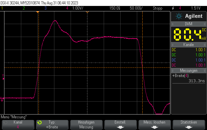
The KNX-TP1 active pulse is 35us long whereas the equalization pulse is 69us long.
Source: NCN5110 datasheet, Figure 16, page 22.
This is a list of a few standard switching MOSFETs from LCSC that I use regularly.
The lists are sorted by ascending size. Power MOSFET is defined as >= 1A continous drain current.
TODO
As far as I can tell from the JST website, JST does not sell any SMD variants of the JST XH series.
However, LCSC lists some 3rd party SMD connectors as VH 3.96mm, such as:
So far I have not tested those and I don’t know yet if they are compatible with the standard JST housings.
Generally, I always recommend going with metal-shielded RJ45 ports since those tend not to break as often.
If you want to buy more than, say, 10pcs, you can check out LCSC’s Ethernet Connectors / Modular Connectors lineup. The very good prices compensate for the shipping fee even when buying only medium quantities.
Note that it’s easy to mix up models with and without magnetics at the moment as there is no suitable filter. It’s easiest to just look at the length of the connector – RJ45 connectors without magnetics are almost cubic in size (i.e. length in the direction where you insert the connector is equal to the width) whereas connectors with magnetics are much longer. Nevertheless, always check the datasheet.
Some examples:
0,89€/pc @ 100pcs0,69€/pc @ 100pcs0.80€/pc @ 100pcs0.11€/pc @100pcs0.14€/pc @ 100pcs0.22€/pc @ 100pcsIn this example, we’ll use the UliEngineering library to compute the gain of a non-inverting OpAmp amplifier, given the two feedback resistor values R1 and R2
In order to install UliEngineering (a Python 3 library) run:
sudo pip3 install -U UliEngineering
We can now use noninverting_amplifier_gain() from the UliEngineering.Electronics.OpAmp package to convert between the units of temperature:
Tip: You can pass both numbers (like 100e3) or strings (such as 100 kΩ) to most UliEngineering functions. SI prefixes like k and m are automatically decoded.
from UliEngineering.Electronics.OpAmp import noninverting_amplifier_gain

# Gain of a non-inverting amplifier with 100k & 10k feedback resistor
gain = noninverting_amplifier_gain(100e3, 10e3)
# gain = 11.0

# ... or you can use strings
gain = noninverting_amplifier_gain("100k", "10k")

# ... or strings with units
gain = noninverting_amplifier_gain("100kΩ", "10kΩ")

# You can also automatically format the result
from UliEngineering.EngineerIO import auto_format
print(auto_format(noninverting_amplifier_gain, "100k", "10k"))
# prints 11.0 V/VAs with most commodity PCB components, LCSC is a good place to find cheap connectors if you want to buy more than 10 pcs or so (due to the shipping fees).
These are listed in AC/DC power connectors. In order to find them quickly, select the Package=Plugin filter and select In Stock and then sort by price (ascending).
Using this method, you can easily find parts such as:
0.0315€/pc @ 100pcs)0.0316€/pc @ 100pcs)Keep in mind that these are not 100% the same regarding their geometry, so always check in the datasheet if they fit your footprint.
You can use this code, for example, in a custom packet handler function.
#include <lwip/prot/ethernet.h>

eth_hdr* hdr = reinterpret_cast<eth_hdr*>(buffer);
auto srcMAC = hdr->src.addr;
auto dstMAC = hdr->dest.addr;

Serial.printf("Received packet: Packet of length %d\n", len);
Serial.printf("    Src MAC: %02X:%02X:%02X:%02X:%02X:%02X\n", srcMAC[0], srcMAC[1], srcMAC[2], srcMAC[3], srcMAC[4], srcMAC[5]);
Serial.printf("    Dst MAC: %02X:%02X:%02X:%02X:%02X:%02X\n", dstMAC[0], dstMAC[1], dstMAC[2], dstMAC[3], dstMAC[4], dstMAC[5]);
Serial.printf("    Our MAC: %02X:%02X:%02X:%02X:%02X:%02X\n", ourEthernetMAC[0], ourEthernetMAC[1], ourEthernetMAC[2], ourEthernetMAC[3], ourEthernetMAC[4], ourEthernetMAC[5]);
The Ethernet packet header is parsed in ethernet_input() in lwip/src/netif/ethernet.c:
By default, esp-idf or the Arduino framework handles incoming Ethernet packets using the
static esp_err_t eth_input_to_netif(esp_eth_handle_t eth_handle, uint8_t *buffer, uint32_t length, void *priv);
function in components/esp_eth/src/esp_eth_netif_glue.c which (besides calling just calls the exported functionesp_netif_receive():
static esp_err_t eth_input_to_netif(esp_eth_handle_t eth_handle, uint8_t *buffer, uint32_t length, void *priv)
{
    return esp_netif_receive((esp_netif_t *)priv, buffer, length, NULL);
}
The function esp_netif_receive() is declared in esp_netif.h and implemented in esp_netif_lwip.c.
This function will call esp_netif->lwip_input_fn(...) on the packet, which will in turn call the interface-type specific .input_fn(...), which is one of
or for wrapped interfaces:
esp_netif_lwip_slip_inputesp_netif_lwip_ppp_inputTypically, you would add a PlatformIO library dependency by adding the following to platformio.ini:
lib_deps =
    bblanchon/ArduinoJson@^6.21.3
but you can also add a git repository (the following example uses the main branch such as master or main):
lib_deps =
    https://github.com/ulikoehler/HumanESPHTTP.git
or you can use a specific branch or tag
lib_deps =
    https://github.com/ulikoehler/HumanESPHTTP.git#v1.0.0
/home/uli/.platformio/packages/[email protected]+2021r2-patch5/bin/../lib/gcc/xtensa-esp32-elf/8.4.0/../../../../xtensa-esp32-elf/bin/ld: .pio/build/esp32dev/libFrameworkArduino.a(main.cpp.o):(.literal._Z8loopTaskPv+0x8): undefined reference to `loop()'
loop() function in your source code. Open main.cpp or your .ino source code file and start with the following (empty) loop() function which does nothing:void loop() {
// Nothing to do here since HTTPServer
// is running in a separate thread
delay(1000);
}void loop() { /* ... */} function to your sourcecode try to build/upload again and the error message should have disappeared.void loop() {
// Nothing to do here since HTTPServer
// is running in a separate thread
Serial.println("Hello world!");
delay(1000);
}
Typically, when you want to use the pio executable from PlatformIO, you need to first activate the virtual environment using
source ~/.platformio/penv/bin/activate
However, you can easily create a shortcut using a shell alias using:
For bash:
echo -e '\nalias platformio="source ~/.platformio/penv/bin/activate"\n' >> ~/.bashrc
For zsh:
echo -e '\nalias platformio="source ~/.platformio/penv/bin/activate"\n' >> ~/.zshrc
Note that in order for the change to take effect, you need to restart your shell (or open a new shell).
Now you can use run
platformio
and you’ll immediately have access to pio and other PlatformIO tools.
You can create a new PlatformIO project on the command line by running e.g.
pio project init --board esp32dev --ide vscode --sample-code
Note that all options (--board and --ide) are optional. Without --sample-code, PlatformIO will not automatically generate src/main.cpp
This will initialize a new PlatformIO project in the current directory.
By default, PlatformIO uses -std=gnu++11 as a compiler flag but you want to use C++17 or C++23 features.
If you just use
build_flags = -std=gnu++17
this will lead to g++ being called with g++ ... -std=gnu++17 ... -std=gnu++11 ... compiler flags. The latter one – gnu++11 i.e. C++11 will take precedence.
In order to activate C++17, use
build_flags = -std=gnu++17
build_unflags = -std=gnu++11
In order to activate C++23 (not fully implemented yet in G++), you currently need to use -std=gnu++2a:
build_flags = -std=gnu++2a
build_unflags = -std=gnu++11
When you try to run a LVGL example such as ST7735R minimal LVGL chart example for PlatformIO on the ESP32, your MCU repeatedly crashes after init (see below for the full crash log) during lv_tlsf_create() which is called inside lv_mem_init()
This crash occurs due to one of the LVGL-related libraries using ps_malloc(), trying to allocate the memory from the external PSRAM chip – which your board does not have (and typically does not need)
In order to fix it, first add the following line to your platformio.ini:
build_flags = -DLV_CONF_INCLUDE_SIMPLE -DLV_CONF_SUPPRESS_DEFINE_CHECK
Now, create a new file include/lv_conf.h which we will use to override the default . This is based on How to use custom LVGL lv_conf.h with Adafruit LittlevGL Glue Library on PlatformIO.
Paste the following content into include/lv_conf.h
/**
 * @file lv_conf.h
 * Configuration file for v8.0.2
 */

/*
 * COPY THIS FILE AS `lv_conf.h` NEXT TO the `lvgl` FOLDER
 */
#if 1 /*Set it to "1" to enable content*/

#ifndef LV_CONF_H
#define LV_CONF_H
/*clang-format off*/

#include <stdint.h>

/*====================
   COLOR SETTINGS
 *====================*/

/*Color depth: 1 (1 byte per pixel), 8 (RGB332), 16 (RGB565), 32 (ARGB8888)*/
#define LV_COLOR_DEPTH 16

/* Swap the 2 bytes of RGB565 color.
 * Useful if the display has a 8 bit interface (e.g. SPI)*/
#if defined(ADAFRUIT_PYPORTAL)
#define LV_COLOR_16_SWAP 1
#else
#define LV_COLOR_16_SWAP 0
#endif

/*Enable more complex drawing routines to manage screens transparency.
 *Can be used if the UI is above another layer, e.g. an OSD menu or video
 *player.
 *Requires `LV_COLOR_DEPTH = 32` colors and the screen's `bg_opa` should be set
 *to non LV_OPA_COVER value*/
#define LV_COLOR_SCREEN_TRANSP 0

/*Images pixels with this color will not be drawn if they are  chroma keyed)*/
#define LV_COLOR_CHROMA_KEY lv_color_hex(0x00ff00) /*pure green*/

/*=========================
   MEMORY SETTINGS
 *=========================*/

/*1: use custom malloc/free, 0: use the built-in `lv_mem_alloc()` and
 * `lv_mem_free()`*/
#define LV_MEM_CUSTOM 0
#if LV_MEM_CUSTOM == 0
/*Size of the memory available for `lv_mem_alloc()` in bytes (>= 2kB)*/
#define LV_MEM_SIZE (32U * 1024U) /*[bytes]*/

/*Set an address for the memory pool instead of allocating it as a normal array.
 * Can be in external SRAM too.*/
#define LV_MEM_ADR 0 /*0: unused*/

// For ESP32, give a memory pool allocator and use the PSRAM instead of flash
#ifdef ESP32
#if LV_MEM_ADR == 0
#define LV_MEM_POOL_INCLUDE <stdlib.h>
#define LV_MEM_POOL_ALLOC malloc
#endif
#endif

#else /*LV_MEM_CUSTOM*/
#define LV_MEM_CUSTOM_INCLUDE                                                  \
  <stdlib.h> /*Header for the dynamic memory function*/
#define LV_MEM_CUSTOM_ALLOC malloc
#define LV_MEM_CUSTOM_FREE free
#define LV_MEM_CUSTOM_REALLOC realloc
#endif /*LV_MEM_CUSTOM*/

/*Use the standard `memcpy` and `memset` instead of LVGL's own functions. (Might
 * or might not be faster).*/
#define LV_MEMCPY_MEMSET_STD 0

/*====================
   HAL SETTINGS
 *====================*/

/*Default display refresh period. LVG will redraw changed ares with this period
 * time*/
#define LV_DISP_DEF_REFR_PERIOD 30 /*[ms]*/

/*Input device read period in milliseconds*/
#define LV_INDEV_DEF_READ_PERIOD 30 /*[ms]*/

/*Use a custom tick source that tells the elapsed time in milliseconds.
 *It removes the need to manually update the tick with `lv_tick_inc()`)*/
#define LV_TICK_CUSTOM 0
#if LV_TICK_CUSTOM
#define LV_TICK_CUSTOM_INCLUDE                                                 \
  "Arduino.h" /*Header for the system time function*/
#define LV_TICK_CUSTOM_SYS_TIME_EXPR                                           \
  (millis()) /*Expression evaluating to current system time in ms*/
#endif       /*LV_TICK_CUSTOM*/

/*Default Dot Per Inch. Used to initialize default sizes such as widgets sized,
 *style paddings. (Not so important, you can adjust it to modify default sizes
 *and spaces)*/
#define LV_DPI_DEF 130 /*[px/inch]*/

/*=======================
 * FEATURE CONFIGURATION
 *=======================*/

/*-------------
 * Drawing
 *-----------*/

/*Enable complex draw engine.
 *Required to draw shadow, gradient, rounded corners, circles, arc, skew lines,
 *image transformations or any masks*/
#define LV_DRAW_COMPLEX 1
#if LV_DRAW_COMPLEX != 0

/*Allow buffering some shadow calculation.
 *LV_SHADOW_CACHE_SIZE is the max. shadow size to buffer, where shadow size is
 *`shadow_width + radius` Caching has LV_SHADOW_CACHE_SIZE^2 RAM cost*/
#define LV_SHADOW_CACHE_SIZE 0
#endif /*LV_DRAW_COMPLEX*/

/*Default image cache size. Image caching keeps the images opened.
 *If only the built-in image formats are used there is no real advantage of
 *caching. (I.e. if no new image decoder is added) With complex image decoders
 *(e.g. PNG or JPG) caching can save the continuous open/decode of images.
 *However the opened images might consume additional RAM.
 *0: to disable caching*/
#define LV_IMG_CACHE_DEF_SIZE 0

/*Maximum buffer size to allocate for rotation. Only used if software rotation
 * is enabled in the display driver.*/
#define LV_DISP_ROT_MAX_BUF (10 * 1024)
/*-------------
 * GPU
 *-----------*/

/*Use STM32's DMA2D (aka Chrom Art) GPU*/
#define LV_USE_GPU_STM32_DMA2D 0
#if LV_USE_GPU_STM32_DMA2D
/*Must be defined to include path of CMSIS header of target processor
e.g. "stm32f769xx.h" or "stm32f429xx.h"*/
#define LV_GPU_DMA2D_CMSIS_INCLUDE
#endif

/*Use NXP's PXP GPU iMX RTxxx platforms*/
#define LV_USE_GPU_NXP_PXP 0
#if LV_USE_GPU_NXP_PXP
/*1: Add default bare metal and FreeRTOS interrupt handling routines for PXP
 *(lv_gpu_nxp_pxp_osa.c) and call lv_gpu_nxp_pxp_init() automatically during
 *lv_init(). Note that symbol SDK_OS_FREE_RTOS has to be defined in order to use
 *FreeRTOS OSA, otherwise bare-metal implementation is selected. 0:
 *lv_gpu_nxp_pxp_init() has to be called manually before lv_init()
 */
#define LV_USE_GPU_NXP_PXP_AUTO_INIT 0
#endif

/*Use NXP's VG-Lite GPU iMX RTxxx platforms*/
#define LV_USE_GPU_NXP_VG_LITE 0

/*-------------
 * Logging
 *-----------*/

/*Enable the log module*/
#define LV_USE_LOG 1
#if LV_USE_LOG

/*How important log should be added:
 *LV_LOG_LEVEL_TRACE       A lot of logs to give detailed information
 *LV_LOG_LEVEL_INFO        Log important events
 *LV_LOG_LEVEL_WARN        Log if something unwanted happened but didn't cause a
 *problem LV_LOG_LEVEL_ERROR       Only critical issue, when the system may fail
 *LV_LOG_LEVEL_USER        Only logs added by the user
 *LV_LOG_LEVEL_NONE        Do not log anything*/
#define LV_LOG_LEVEL LV_LOG_LEVEL_INFO

/*1: Print the log with 'printf';
 *0: User need to register a callback with `lv_log_register_print_cb()`*/
#define LV_LOG_PRINTF 0

/*Enable/disable LV_LOG_TRACE in modules that produces a huge number of logs*/
#define LV_LOG_TRACE_MEM 1
#define LV_LOG_TRACE_TIMER 1
#define LV_LOG_TRACE_INDEV 1
#define LV_LOG_TRACE_DISP_REFR 1
#define LV_LOG_TRACE_EVENT 1
#define LV_LOG_TRACE_OBJ_CREATE 1
#define LV_LOG_TRACE_LAYOUT 1
#define LV_LOG_TRACE_ANIM 1

#endif /*LV_USE_LOG*/

/*-------------
 * Asserts
 *-----------*/

/*Enable asserts if an operation is failed or an invalid data is found.
 *If LV_USE_LOG is enabled an error message will be printed on failure*/
#define LV_USE_ASSERT_NULL                                                     \
  1 /*Check if the parameter is NULL. (Very fast, recommended)*/
#define LV_USE_ASSERT_MALLOC                                                   \
  1 /*Checks is the memory is successfully allocated or no. (Very fast,        \
       recommended)*/
#define LV_USE_ASSERT_STYLE                                                    \
  0 /*Check if the styles are properly initialized. (Very fast, recommended)*/
#define LV_USE_ASSERT_MEM_INTEGRITY                                            \
  0 /*Check the integrity of `lv_mem` after critical operations. (Slow)*/
#define LV_USE_ASSERT_OBJ                                                      \
  0 /*Check the object's type and existence (e.g. not deleted). (Slow)*/

/*Add a custom handler when assert happens e.g. to restart the MCU*/
#define LV_ASSERT_HANDLER_INCLUDE <stdint.h>
#define LV_ASSERT_HANDLER                                                      \
  while (1)                                                                    \
    ; /*Halt by default*/

/*-------------
 * Others
 *-----------*/

/*1: Show CPU usage and FPS count in the right bottom corner*/
#define LV_USE_PERF_MONITOR 0

/*1: Show the used memory and the memory fragmentation  in the left bottom
 * corner Requires LV_MEM_CUSTOM = 0*/
#define LV_USE_MEM_MONITOR 0

/*1: Draw random colored rectangles over the redrawn areas*/
#define LV_USE_REFR_DEBUG 0

/*Change the built in (v)snprintf functions*/
#define LV_SPRINTF_CUSTOM 0
#if LV_SPRINTF_CUSTOM
#define LV_SPRINTF_INCLUDE <stdio.h>
#define lv_snprintf snprintf
#define lv_vsnprintf vsnprintf
#else /*LV_SPRINTF_CUSTOM*/
#define LV_SPRINTF_USE_FLOAT 0
#endif /*LV_SPRINTF_CUSTOM*/

#define LV_USE_USER_DATA 1

/*Garbage Collector settings
 *Used if lvgl is binded to higher level language and the memory is managed by
 *that language*/
#define LV_ENABLE_GC 0
#if LV_ENABLE_GC != 0
#define LV_GC_INCLUDE "gc.h" /*Include Garbage Collector related things*/
#endif                       /*LV_ENABLE_GC*/

/*=====================
 *  COMPILER SETTINGS
 *====================*/

/*For big endian systems set to 1*/
#define LV_BIG_ENDIAN_SYSTEM 0

/*Define a custom attribute to `lv_tick_inc` function*/
#ifdef ESP32
#define LV_ATTRIBUTE_TICK_INC IRAM_ATTR
#else
#define LV_ATTRIBUTE_TICK_INC
#endif

/*Define a custom attribute to `lv_timer_handler` function*/
#define LV_ATTRIBUTE_TIMER_HANDLER

/*Define a custom attribute to `lv_disp_flush_ready` function*/
#define LV_ATTRIBUTE_FLUSH_READY

/*Required alignment size for buffers*/
#define LV_ATTRIBUTE_MEM_ALIGN_SIZE

/*Will be added where memories needs to be aligned (with -Os data might not be
 * aligned to boundary by default). E.g. __attribute__((aligned(4)))*/
#define LV_ATTRIBUTE_MEM_ALIGN

/*Attribute to mark large constant arrays for example font's bitmaps*/
#define LV_ATTRIBUTE_LARGE_CONST

/*Complier prefix for a big array declaration in RAM*/
#define LV_ATTRIBUTE_LARGE_RAM_ARRAY

/*Place performance critical functions into a faster memory (e.g RAM)*/
#ifdef ESP32
#define LV_ATTRIBUTE_FAST_MEM IRAM_ATTR
#else
#define LV_ATTRIBUTE_FAST_MEM
#endif

/*Prefix variables that are used in GPU accelerated operations, often these need
 * to be placed in RAM sections that are DMA accessible*/
#define LV_ATTRIBUTE_DMA

/*Export integer constant to binding. This macro is used with constants in the
 *form of LV_<CONST> that should also appear on LVGL binding API such as
 *Micropython.*/
#define LV_EXPORT_CONST_INT(int_value)                                         \
  struct _silence_gcc_warning /*The default value just prevents GCC warning*/

/*Extend the default -32k..32k coordinate range to -4M..4M by using int32_t for
 * coordinates instead of int16_t*/
#define LV_USE_LARGE_COORD 0

/*==================
 *   FONT USAGE
 *===================*/

/*Montserrat fonts with ASCII range and some symbols using bpp = 4
 *https://fonts.google.com/specimen/Montserrat*/
#define LV_FONT_MONTSERRAT_8 0
#define LV_FONT_MONTSERRAT_10 0
#define LV_FONT_MONTSERRAT_12 0
#define LV_FONT_MONTSERRAT_14 1
#define LV_FONT_MONTSERRAT_16 0
#define LV_FONT_MONTSERRAT_18 0
#define LV_FONT_MONTSERRAT_20 0
#define LV_FONT_MONTSERRAT_22 0
#define LV_FONT_MONTSERRAT_24 0
#define LV_FONT_MONTSERRAT_26 0
#define LV_FONT_MONTSERRAT_28 0
#define LV_FONT_MONTSERRAT_30 0
#define LV_FONT_MONTSERRAT_32 0
#define LV_FONT_MONTSERRAT_34 0
#define LV_FONT_MONTSERRAT_36 0
#define LV_FONT_MONTSERRAT_38 0
#define LV_FONT_MONTSERRAT_40 0
#define LV_FONT_MONTSERRAT_42 0
#define LV_FONT_MONTSERRAT_44 0
#define LV_FONT_MONTSERRAT_46 0
#define LV_FONT_MONTSERRAT_48 0

/*Demonstrate special features*/
#define LV_FONT_MONTSERRAT_12_SUBPX 0
#define LV_FONT_MONTSERRAT_28_COMPRESSED 0 /*bpp = 3*/
#define LV_FONT_DEJAVU_16_PERSIAN_HEBREW                                       \
  0 /*Hebrew, Arabic, Perisan letters and all their forms*/
#define LV_FONT_SIMSUN_16_CJK 0 /*1000 most common CJK radicals*/

/*Pixel perfect monospace fonts*/
#define LV_FONT_UNSCII_8 0
#define LV_FONT_UNSCII_16 0

/*Optionally declare custom fonts here.
 *You can use these fonts as default font too and they will be available
 *globally. E.g. #define LV_FONT_CUSTOM_DECLARE   LV_FONT_DECLARE(my_font_1)
 *LV_FONT_DECLARE(my_font_2)*/
#define LV_FONT_CUSTOM_DECLARE

/*Always set a default font*/
#define LV_FONT_DEFAULT &lv_font_montserrat_14

/*Enable handling large font and/or fonts with a lot of characters.
 *The limit depends on the font size, font face and bpp.
 *Compiler error will be triggered if a font needs it.*/
#define LV_FONT_FMT_TXT_LARGE 0

/*Enables/disables support for compressed fonts.*/
#define LV_USE_FONT_COMPRESSED 0

/*Enable subpixel rendering*/
#define LV_USE_FONT_SUBPX 0
#if LV_USE_FONT_SUBPX
/*Set the pixel order of the display. Physical order of RGB channels. Doesn't
 * matter with "normal" fonts.*/
#define LV_FONT_SUBPX_BGR 0 /*0: RGB; 1:BGR order*/
#endif

/*=================
 *  TEXT SETTINGS
 *=================*/

/**
 * Select a character encoding for strings.
 * Your IDE or editor should have the same character encoding
 * - LV_TXT_ENC_UTF8
 * - LV_TXT_ENC_ASCII
 */
#define LV_TXT_ENC LV_TXT_ENC_UTF8

/*Can break (wrap) texts on these chars*/
#define LV_TXT_BREAK_CHARS " ,.;:-_"

/*If a word is at least this long, will break wherever "prettiest"
 *To disable, set to a value <= 0*/
#define LV_TXT_LINE_BREAK_LONG_LEN 0

/*Minimum number of characters in a long word to put on a line before a break.
 *Depends on LV_TXT_LINE_BREAK_LONG_LEN.*/
#define LV_TXT_LINE_BREAK_LONG_PRE_MIN_LEN 3

/*Minimum number of characters in a long word to put on a line after a break.
 *Depends on LV_TXT_LINE_BREAK_LONG_LEN.*/
#define LV_TXT_LINE_BREAK_LONG_POST_MIN_LEN 3

/*The control character to use for signalling text recoloring.*/
#define LV_TXT_COLOR_CMD "#"

/*Support bidirectional texts. Allows mixing Left-to-Right and Right-to-Left
 *texts. The direction will be processed according to the Unicode Bidirectioanl
 *Algorithm:
 *https://www.w3.org/International/articles/inline-bidi-markup/uba-basics*/
#define LV_USE_BIDI 0
#if LV_USE_BIDI
/*Set the default direction. Supported values:
 *`LV_BASE_DIR_LTR` Left-to-Right
 *`LV_BASE_DIR_RTL` Right-to-Left
 *`LV_BASE_DIR_AUTO` detect texts base direction*/
#define LV_BIDI_BASE_DIR_DEF LV_BASE_DIR_AUTO
#endif

/*Enable Arabic/Persian processing
 *In these languages characters should be replaced with an other form based on
 *their position in the text*/
#define LV_USE_ARABIC_PERSIAN_CHARS 0

/*==================
 *  WIDGET USAGE
 *================*/

/*Documentation of the widgets:
 * https://docs.lvgl.io/latest/en/html/widgets/index.html*/

#define LV_USE_ARC 1

#define LV_USE_ANIMIMG 1

#define LV_USE_BAR 1

#define LV_USE_BTN 1

#define LV_USE_BTNMATRIX 1

#define LV_USE_CANVAS 1

#define LV_USE_CHECKBOX 1

#define LV_USE_DROPDOWN 1 /*Requires: lv_label*/

#define LV_USE_IMG 1 /*Requires: lv_label*/

#define LV_USE_LABEL 1
#if LV_USE_LABEL
#define LV_LABEL_TEXT_SELECTION 1 /*Enable selecting text of the label*/
#define LV_LABEL_LONG_TXT_HINT                                                 \
  1 /*Store some extra info in labels to speed up drawing of very long texts*/
#endif

#define LV_USE_LINE 1

#define LV_USE_ROLLER 1 /*Requires: lv_label*/
#if LV_USE_ROLLER
#define LV_ROLLER_INF_PAGES                                                    \
  7 /*Number of extra "pages" when the roller is infinite*/
#endif

#define LV_USE_SLIDER 1 /*Requires: lv_bar*/

#define LV_USE_SWITCH 1

#define LV_USE_TEXTAREA 1 /*Requires: lv_label*/
#if LV_USE_TEXTAREA != 0
#define LV_TEXTAREA_DEF_PWD_SHOW_TIME 1500 /*ms*/
#endif

#define LV_USE_TABLE 1

/*==================
 * EXTRA COMPONENTS
 *==================*/

/*-----------
 * Widgets
 *----------*/
#define LV_USE_CALENDAR 1
#if LV_USE_CALENDAR
#define LV_CALENDAR_WEEK_STARTS_MONDAY 0
#if LV_CALENDAR_WEEK_STARTS_MONDAY
#define LV_CALENDAR_DEFAULT_DAY_NAMES                                          \
  { "Mo", "Tu", "We", "Th", "Fr", "Sa", "Su" }
#else
#define LV_CALENDAR_DEFAULT_DAY_NAMES                                          \
  { "Su", "Mo", "Tu", "We", "Th", "Fr", "Sa" }
#endif

#define LV_CALENDAR_DEFAULT_MONTH_NAMES                                        \
  {                                                                            \
    "January", "February", "March", "April", "May", "June", "July", "August",  \
        "September", "October", "November", "December"                         \
  }
#define LV_USE_CALENDAR_HEADER_ARROW 1
#define LV_USE_CALENDAR_HEADER_DROPDOWN 1
#endif /*LV_USE_CALENDAR*/

#define LV_USE_CHART 1

#define LV_USE_COLORWHEEL 1

#define LV_USE_IMGBTN 1

#define LV_USE_KEYBOARD 1

#define LV_USE_LED 1

#define LV_USE_LIST 1

#define LV_USE_METER 1

#define LV_USE_MSGBOX 1

#define LV_USE_SPINBOX 1

#define LV_USE_SPINNER 1

#define LV_USE_TABVIEW 1

#define LV_USE_TILEVIEW 1

#define LV_USE_WIN 1

#define LV_USE_SPAN 1
#if LV_USE_SPAN
/*A line text can contain maximum num of span descriptor */
#define LV_SPAN_SNIPPET_STACK_SIZE 64
#endif

/*-----------
 * Themes
 *----------*/
/*A simple, impressive and very complete theme*/
#define LV_USE_THEME_DEFAULT 1
#if LV_USE_THEME_DEFAULT

/*0: Light mode; 1: Dark mode*/
#define LV_THEME_DEFAULT_DARK 0

/*1: Enable grow on press*/
#define LV_THEME_DEFAULT_GROW 1

/*Default transition time in [ms]*/
#define LV_THEME_DEFAULT_TRANSITON_TIME 80
#endif /*LV_USE_THEME_DEFAULT*/

/*An very simple them that is a good starting point for a custom theme*/
#define LV_USE_THEME_BASIC 1

/*A theme designed for monochrome displays*/
#define LV_USE_THEME_MONO 1

/*-----------
 * Layouts
 *----------*/

/*A layout similar to Flexbox in CSS.*/
#define LV_USE_FLEX 1

/*A layout similar to Grid in CSS.*/
#define LV_USE_GRID 1

/*==================
 * EXAMPLES
 *==================*/

/*Enable the examples to be built with the library*/
#define LV_BUILD_EXAMPLES 1

/*--END OF LV_CONF_H--*/

#endif /*LV_CONF_H*/

#endif /*End of "Content enable"*/
and now retry uploading your program.
void lv_mem_init(void)
{
    // ...
    tlsf = lv_tlsf_create_with_pool((void *)LV_MEM_POOL_ALLOC(LV_MEM_SIZE), LV_MEM_SIZE);
    // ...
}
with LV_MEM_POOL_ALLOC(LV_MEM_SIZE), by default, expanding to ps_malloc – in other words, your ESP32 will try to allocate it from the PSRAM.
We fixed this by defining, in our custom lv_conf.h, the following:
#define LV_MEM_POOL_INCLUDE <stdlib.h>
#define LV_MEM_POOL_ALLOC malloc
instead of the default
#define LV_MEM_POOL_INCLUDE <esp32-hal-psram.h>
#define LV_MEM_POOL_ALLOC ps_malloc
The compiler flags are required to fix issues relating to LVGL expecting lv_conf.h to be at a specific location.
(gdb) i sym 0x400dedf0
lv_tlsf_create + 36 in section .flash.text
(gdb) i sym  0x400d4ce3
lv_init + 43 in section .flash.text
(gdb) i sym 0x400f4506
Adafruit_LvGL_Glue::begin(Adafruit_SPITFT*, void*, bool) + 6 in section .flash.text
Rebooting...
ets Jun  8 2016 00:22:57

rst:0xc (SW_CPU_RESET),boot:0x13 (SPI_FAST_FLASH_BOOT)
configsip: 0, SPIWP:0xee
clk_drv:0x00,q_drv:0x00,d_drv:0x00,cs0_drv:0x00,hd_drv:0x00,wp_drv:0x00
mode:DIO, clock div:2
load:0x3fff0030,len:1184
load:0x40078000,len:13192
load:0x40080400,len:3028
entry 0x400805e4
Guru Meditation Error: Core  1 panic'ed (StoreProhibited). Exception was unhandled.

Core  1 register dump:
PC      : 0x400dedfb  PS      : 0x00060830  A0      : 0x800dee25  A1      : 0x3ffb2180
A2      : 0x00000000  A3      : 0x00000000  A4      : 0x0000001b  A5      : 0x00060e23
A6      : 0x007bf388  A7      : 0x003fffff  A8      : 0x00000000  A9      : 0x00000000
A10     : 0x00000480  A11     : 0x00000000  A12     : 0x0000000e  A13     : 0x3ffbcc50
A14     : 0x00000003  A15     : 0x00060023  SAR     : 0x00000005  EXCCAUSE: 0x0000001d
EXCVADDR: 0x00000008  LBEG    : 0x40089691  LEND    : 0x400896a1  LCOUNT  : 0xfffffff5


Backtrace: 0x400dedf8:0x3ffb2180 0x400dee22:0x3ffb21a0 0x400dd607:0x3ffb21c0 0x400d4ceb:0x3ffb21e0 0x400f450e:0x3ffb2200 0x400f462b:0x3ffb2250 0x400d23f9:0x3ffb2270 0x400f54a2:0x3ffb2290
If you use PlatformIO with the Adafruit LittlevGL Glue Library as we did in our LVGL examples such as Adafruit ST7735R display minimal LVGL example for PlatformIO, lv_conf.h comes with the Adafruit LittlevGL Glue Library, hence any changes to lv_conf.h would not be permanent as they would be overwritten when the library inside the .pio folder is re-installed.
The original config file is located at
.pio/libdeps/esp32dev/Adafruit LittlevGL Glue Library/lv_conf.h
(esp32dev is the environment name in your platformio.ini and hence might be different in your configuration)
lv_conf.hLuckily, PlatformIO configures the project’s include directory to have precedence over other folders, including the library dependencies located in .pio.
In other words, you simply have to create a file called lv_conf.h in your project’s include directory and PlatformIO will handle the rest for you.
Typically, just copy the content from the original lv_conf.h to get started and then make your modifications.
Furthermore, to suppress some internal errors, you need to add the following #defines/compiler flags to your platformio.ini:
build_flags = -DLV_CONF_INCLUDE_SIMPLE -DLV_CONF_SUPPRESS_DEFINE_CHECK
The following configuration works for flashing the Arduino Uno with the AVRISP MKII:
[env:uno]
platform = atmelavr
board = uno
framework = arduino
upload_protocol= custom
upload_port = usb
upload_flags =
   -C
   $PROJECT_PACKAGES_DIR/tool-avrdude/avrdude.conf
   -p
   $BOARD_MCU
   -P
   $UPLOAD_PORT
   -c
   avrispmkII
 ;   -c stk500v2
upload_command = avrdude $UPLOAD_FLAGS -U flash:w:$SOURCE:i
In our previous post, we used NOP instructions inserted in between direct GPIO register access instructions to create pulse widths variable with obtainable resolutions of 62.5ns.
One could now use a for loop to create multiple NOP instructions:
for (int i = 0; i < 3; i++)
{
    _NOP();
}
As a matter of fact, this performs exactly as using three NOPs manually (312.5ns pulse width) because it is inlined by the compiler, i.e. the compiler just generates three separate NOPs since the number of NOPs is known at compile time.
Were we instead to use a variable numNOPs and use volatile so the compiler is instructed to not assume it is constant:
volatile int numNOPs = 3;
for (int i = 0; i < numNOPs; i++)
{
  _NOP();
}
we’ll end up with a pulse width of not 312.5ns but 3250ns:
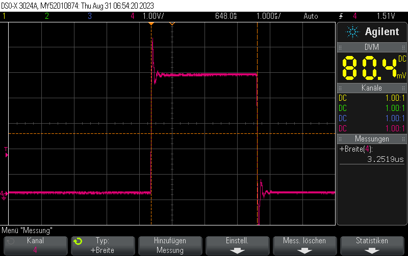
I measured the pulse width for different numNOPs settings:
numNOPs = 1: 1.50us pulse widthnumNOPs = 2: 2.25us pulse widthnumNOPs = 3: 3.00us pulse widthnumNOPs = 4: 3.75us pulse widthnumNOPs = 5: 4.5us pulse widthnumNOPs = 6: 5.25us pulse widthnumNOPs = 7: 6.00us pulse widthnumNOPs = 8: 6.75us pulse widthnumNOPs = 9: 7.5us pulse widthnumNOPs = 10: 8.25us pulse widthFrom this table it is obvious that the formula for the pulse width is
(\text{numNOPs} + 1) \cdot 0.75usWhy is it so much slower than manually pasting NOPs into it? Because the for loop introduces many additional instructions including memory load, compare and (conditional) jump into the machine instructions for your compiled program. This is why instead of 1instruction of length 62.5ns it actually takes 12 instructions of length 750ns to complete one iteration of the loop.
#include <Arduino.h>
#include <avr/io.h>

#define PORT11 PORTB
#define PIN11 3
#define PIN11_MASK (1 << PIN11)

void setup() {
    pinMode(11, OUTPUT);
}

volatile int numNOPs  = 1;

void loop() {
    cli();
    PORT11 |= PIN11_MASK;
    for (int i = 0; i < numNOPs; i++) {
        _NOP();
    }
    PORT11 &= ~PIN11_MASK;
    sei();

    delay(10);
}
In our previous post Short pulse generation with Arduino Uno Part 2: GPIO register access pulse width we detailed how to generate extremely short 125ns pulses using direct GPIO port register writes.
Given the code from our previous post, the pulse length can be varied with fairly high resolution using a NOPinstruction.
A NOP instruction is a machine instruction for the microcontroller which does nothing (but doing nothing via NOP takes exactly one CPU cycle, which in effect leads to a very small delay). The delay is equivalent to one clock cycle – at 16 MHz master clock frequency such as for the Arduino Uno, this equates to 1/16MHz = 62.5ns.
We can integrate NOP into our code from the previous post by using the _NOP() macro which is available in #include <avr/cpufunc.h>
#define PORT11 PORTB
#define PIN11 3
#define PIN11_MASK (1 << PIN11)
void loop() {
cli(); // Disable interrupts
PORT11 |= PIN11_MASK; // Turn pin 11 on
_NOP();
PORT11 &= ~PIN11_MASK; // Turn pin 11 off
sei(); // Enable interrupts again
delay(10); // Wait 10ms
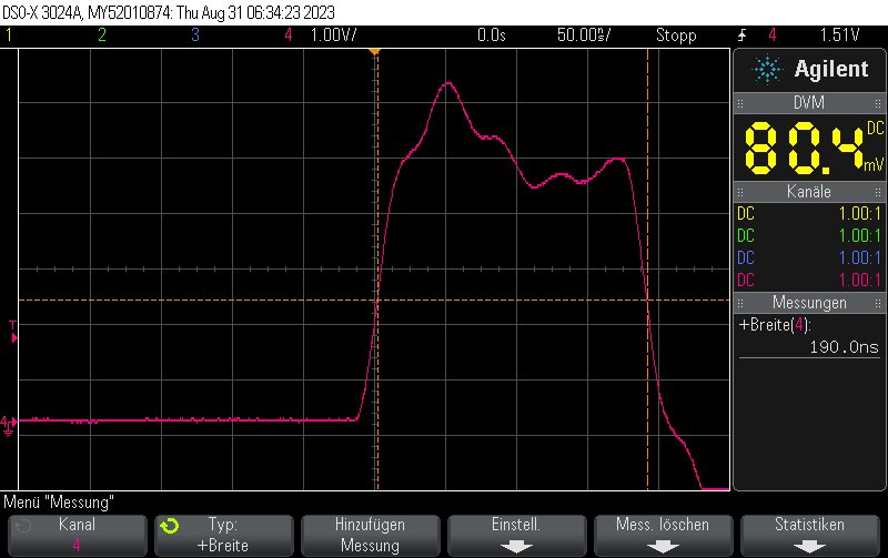
}The original code without NOPs generated pulsed 125ns in width.
With one NOP instruction, it generates pulses 125ns + 62.5ns = 187.5ns in width:
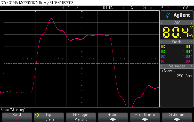
Similarly, if we use two NOPs:
cli(); // Disable interrupts
PORT11 |= PIN11_MASK; // Turn pin 11 on
_NOP();
_NOP();
PORT11 &= ~PIN11_MASK; // Turn pin 11 off
sei(); // Enable interrupts again
we will obtain pulses 125ns + 2*62.5ns = 250ns in width:
With three NOPs we’ll se pulses 125ns + 3*62.5ns = 312.5ns in width
#include <Arduino.h>
#include <avr/io.h>

#define PORT11 PORTB
#define PIN11 3
#define PIN11_MASK (1 << PIN11)

void setup() {
    pinMode(11, OUTPUT);
}

void loop() {
    cli();
    PORT11 |= PIN11_MASK;
    _NOP();
    _NOP();
    _NOP();
    PORT11 &= ~PIN11_MASK;
    sei();

    delay(10);
}