Programming languages

CadQuery: How to fix cq.Location() error: TypeError: Expected three floats, OCC gp_, or 3-tuple

Problem

You are trying to construct a cq.Location object using code like

cq.Location(1, 2, 3)

however when you run it, you see the following error message:

File ~\AppData\Local\Packages\PythonSoftwareFoundation.Python.3.9_qbz5n2kfra8p0\LocalCache\local-packages\Python39\site-packages\cadquery\occ_impl\geom.py:1011, in Location.__init__(self, *args)
   1008 else:
   1009     t, ax, angle = args
   1010     T.SetRotation(
-> 1011         gp_Ax1(Vector().toPnt(), Vector(ax).toDir()), angle * math.pi / 180.0
   1012     )
   1013     T.SetTranslationPart(Vector(t).wrapped)
   1015 self.wrapped = TopLoc_Location(T)

File ~\AppData\Local\Packages\PythonSoftwareFoundation.Python.3.9_qbz5n2kfra8p0\LocalCache\local-packages\Python39\site-packages\cadquery\occ_impl\geom.py:91, in Vector.__init__(self, *args)
     89         fV = gp_Vec(args[0])
     90     else:
---> 91         raise TypeError("Expected three floats, OCC gp_, or 3-tuple")
     92 elif len(args) == 0:
     93     fV = gp_Vec(0, 0, 0)

TypeError: Expected three floats, OCC gp_, or 3-tuple

Solution:

Don’t pass three separate parameters to cq.Location() – pass a tuple with three numbers by adding an additional set of braces:

cq.Location((1, 2, 3))


Posted by Uli Köhler in CadQuery, Python

CadQuery: Asymmetric chamfer minimal example

import cadquery as cq

obj = cq.Workplane("XY").box(1,1,3)
# Add chamfer to only the top face edges parallel to the X axis
obj = obj.faces("+Z").edges("|X").chamfer(0.8, 0.3)
obj

Posted by Uli Köhler in CadQuery, Python

CadQuery: How to chamfer only two opposing edges of top face

import cadquery as cq

obj = cq.Workplane("XY").box(1,1,3)
# Add chamfer to only the top face edges parallel to the X axis
obj = obj.faces("+Z").edges("|X").chamfer(0.2)
obj

Posted by Uli Köhler in CadQuery, Python

CadQuery: How to chamfer top face of object

import cadquery as cq

obj = cq.Workplane("XY").box(1,1,3)
# Add chamfer to all top face edges
obj = obj.faces("+Z").chamfer(0.2)
obj

Posted by Uli Köhler in CadQuery, Python

CadQuery: Chamfer in sketch minimal example

This code chamfers the top side of a sketch rectangle, which is then extruded

import cadquery as cq

obj = (cq.Workplane("YZ")
    .sketch()
    .rect(1,4)
    # Select vertices to chamfer
    .vertices(">Y") # Top of local Y coordinate system (which is Z axis)
    .chamfer(0.2)
    .finalize()
    .extrude(0.1)
)
obj

Posted by Uli Köhler in CadQuery, Python

CadQuery minimal sketch from segment() lines example

This code creates a sketch from four segment lines forming a rectangle (given the four sets of X/Y coordinates). The segments are then assembled into a face and extruded.

import cadquery as cq

xstart = 1.0
height = 4.0
width = 1.0
obj = (cq.Workplane("YZ")
    .sketch()
    .segment((xstart, 0), (xstart, height))
    .segment((xstart + width, height))
    .segment((xstart + width, 0))
    .close()
    .assemble(tag="face")
    .finalize()
    .extrude(0.1)
)
obj

Posted by Uli Köhler in CadQuery, Python

CadQuery sketch: How to move to different location

In order to move to a certain position in a CadQuery sketch, use .push(cq.Location(...))

Full example

import cadquery as cq

# Create workplane (2d coordinate system for us to create the sketch in)
wp = cq.Workplane("XY")
# Create sketch
result = wp.sketch().push(cq.Location((1,0.5,0))).rect(1,1).finalize().extrude(0.1)

result # This line is just to show the result in cq-editor or jupyter

Posted by Uli Köhler in CadQuery, Python

CadQuery minimal rectangular array (rarray) example

This example generates a 2x2 grid of 1x1mm rectangles in a sketch, then extrudes it

import cadquery as cq

# Create workplane (2d coordinate system for us to create the sketch in)
wp = cq.Workplane("XY")
# Create sketch & extrude
result = wp.sketch().rarray(
    1.5, # X distance between center points of rectangles
    1.5, # Y distance between center points of rectangles
    2, # Number of rectangles in X direction
    2 # Number of rectangles in Y direction
).rect(1,1).finalize().extrude(0.1)

result # This line is just to show the result in cq-editor or jupyter

Posted by Uli Köhler in CadQuery, Python

CadQuery: How to move/translate extruded sketch

In our previous example CadQuery minimal sketch extrude example we showed how to create and extrude a simple sketch.

You can translate this easily using

result = result.translate(cq.Vector(1,0,0))

Full example

import cadquery as cq

# Create workplane (2d coordinate system for us to create the sketch in)
wp = cq.Workplane("XY")
# Create sketch, create rect, close sketch and extrude the resulting face
result = wp.sketch().rect(2, 2).finalize().extrude(0.1)
result = result.translate(cq.Vector(1,0,0))

result # This line is just to show the result in cq-editor or jupyter

Posted by Uli Köhler in CadQuery, Python

CadQuery minimal sketch extrude example

The folllowing example creates a sketch in the XY plane, creates a 2x2mm rectangle in said sketch and extrudes it to a height of 0.1mm.

import cadquery as cq

# Create workplane (2d coordinate system for us to create the sketch in)
wp = cq.Workplane("XY")
# Create sketch, create rect, close sketch and extrude the resulting face
result = wp.sketch().rect(2, 2).finalize().extrude(0.1)

result # This line is just to show the result in cq-editor or jupyter

Posted by Uli Köhler in CadQuery, Python

CadQuery simple L-shaped piece example (with STEP export)

import cadquery as cq

# Define dimensions
base_length = 200  # 20cm
base_width = 80    # 8cm
plate_thickness = 2  # 2mm
upright_height = 400  # 40cm

# Create the base plate
base_plate = cq.Workplane("XY").box(base_length, base_width, plate_thickness)

# Create the upright plate
# Position is set such that it aligns with the end of the base plate and stands upright
upright_plate = cq.Workplane("XY").workplane(offset=plate_thickness).transformed(rotate=(0, 90, 0)).box(upright_height, base_width, plate_thickness).translate((base_length/2, 0, upright_height/2))

# Join the two parts into one
final_part = base_plate.union(upright_plate)

# Export to STEP
final_part.val().exportStep("L-piece.stp")


Posted by Uli Köhler in CadQuery, Python

Jupyter adjustment widgets with plus and minus buttons

First, define get and set functions:

# Basic examples for get and set value functions

def get_value(): # will only be used to get the initial value
    return httpx.get(f"http://{ip}/api/get-value").json()["value"]

def set_value(value):
    httpx.get(f"http://{ip}/api/set-value?nedge={value}")


import ipywidgets as widgets
from IPython.display import display

# Step 2: Define the widget components
value_display = widgets.IntText(value=get_value(), description='Value:', disabled=False)
plus_button = widgets.Button(description='+')
minus_button = widgets.Button(description='-')

def on_value_change(change):
    set_value(change['new'])
    
value_display.observe(on_value_change, names='value')

# Step 4: Define the update functions
def on_plus_button_clicked(b):
    value_display.value += 1

def on_minus_button_clicked(b):
    value_display.value -= 1

# Step 5: Bind the update functions to the buttons
plus_button.on_click(on_plus_button_clicked)
minus_button.on_click(on_minus_button_clicked)

# Step 6: Display the widgets
widgets_layout = widgets
display(value_display, plus_button, minus_button)


Posted by Uli Köhler in Jupyter, Python

STM32H743 DAC instant switch off (no fall time)

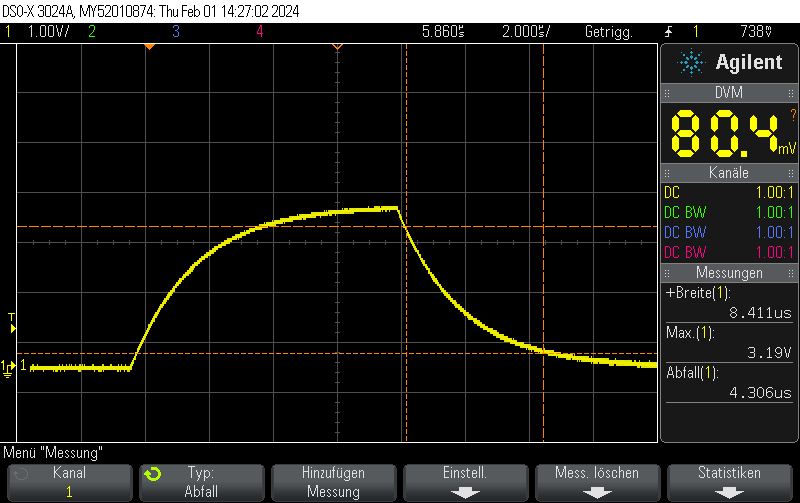
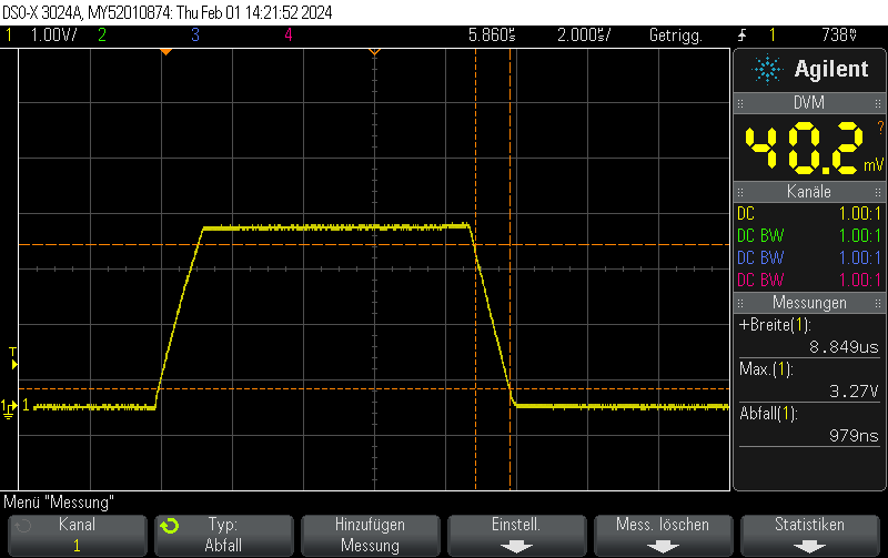
In our previous post STM32H743 DAC rise/fall time experiments we showed that the STM23H743 has relatively long turn-on / turn-off times of approximately 950 nanoseconds, limiting the generation of fast rectangular signals:

However, there’s a trick how to obtain fall times almost 3 orders of magnitude better for the special case of switching either to full-scale VDD or to GND.

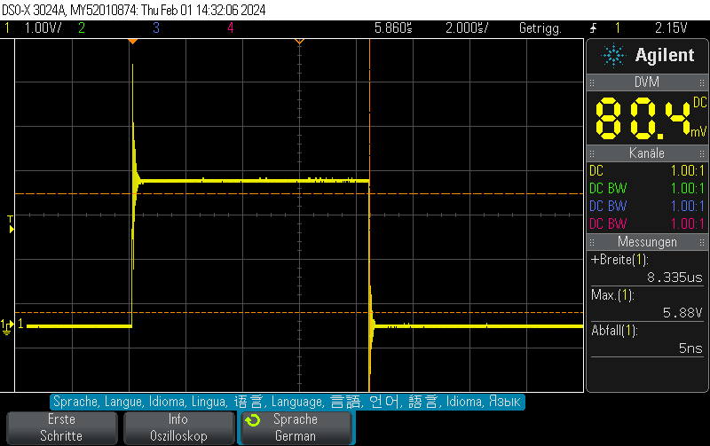
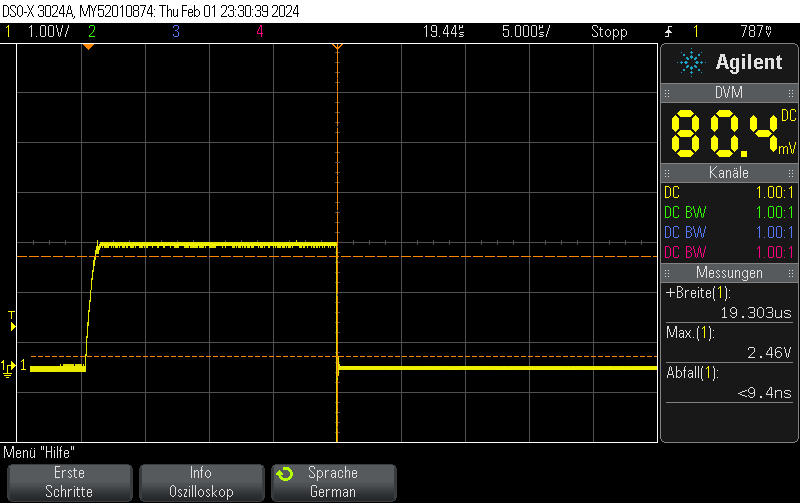
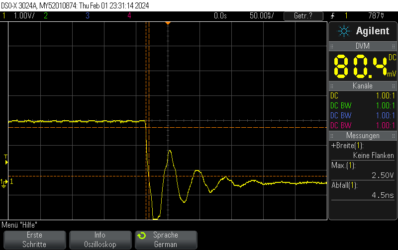
Instead of setting the DAC to the new value, you can just disable the DAC and let the GPIO take care of the rest. This allows for extremely fast fall times of approximately 5ns.

Note that switching the GPIO to digital mode while the DAC is on does not seem to have any effect.

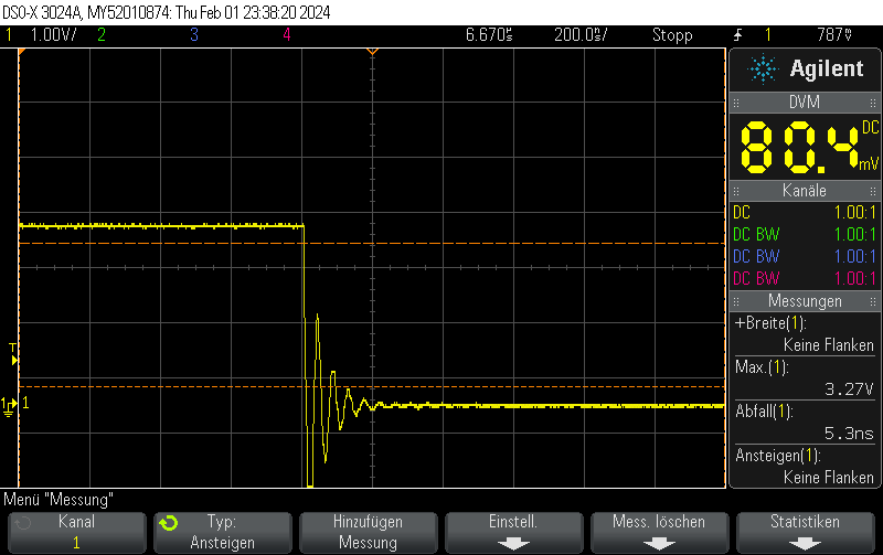
Please note that I didn’t take any care to make the measurement setup immune to the high transients, leading to some oscillation. You should take your own measurements if you have specific requirements.

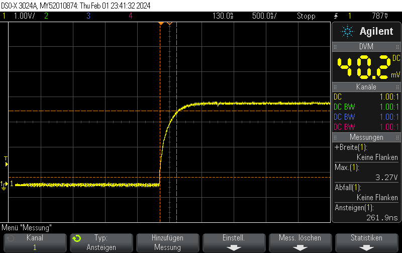
DAC fall time from 3/4 full scale value (3072)

Note that switching on the DAC quickly is outside the scope of this post, but when toggling the DAC enable bit, you can still obtain 250ns rise times pretty easily.

Code example

void Init() {    
    DAC_ChannelConfTypeDef sConfig = {0};

    // Initialize DAC
    hdac.Instance = DAC1;
    if (HAL_DAC_Init(&hdac) != HAL_OK)
    {
        // Initialization Error
        __BKPT();
    }

    // Configure DAC channel
    sConfig.DAC_Trigger = DAC_TRIGGER_NONE;  // No trigger, free-running mode
    sConfig.DAC_OutputBuffer = DAC_OUTPUTBUFFER_ENABLE;

    if (HAL_DAC_ConfigChannel(&hdac, &sConfig, DAC_CHANNEL_1) != HAL_OK)
    {
        // Channel configuration Error
        __BKPT();
    }

    // Enable DAC Channel and start the conversion
    if (HAL_DAC_Start(&hdac, DAC_CHANNEL_1) != HAL_OK)
    {
        // Starting Error
        __BKPT();
    }

    // Set DAC to some value, which won't be changed for this example
    if (HAL_DAC_SetValue(&hdac, DAC_CHANNEL_1, DAC_ALIGN_12B_R, 3072) != HAL_OK)
    {
        // Setting DAC value Error
         __BKPT();
    }
}
void Pulse_On() {
    // Enable DAC
    hdac.Instance->CR |= DAC_CR_EN1;

    // Set GPIO to analog mode
    GPIO_InitTypeDef GPIO_InitStruct = {0};
    GPIO_InitStruct.Pin = GPIO_PIN_4;
    GPIO_InitStruct.Mode = GPIO_MODE_ANALOG;
    GPIO_InitStruct.Speed = GPIO_SPEED_FREQ_VERY_HIGH;
    GPIO_InitStruct.Pull = GPIO_NOPULL;
    HAL_GPIO_Init(GPIOA, &GPIO_InitStruct);
}

void Pulse_Off() {
    GPIO_InitTypeDef GPIO_InitStruct = {0};
    GPIO_InitStruct.Pin = GPIO_PIN_4;
    GPIO_InitStruct.Mode = GPIO_MODE_OUTPUT_PP;
    GPIO_InitStruct.Speed = GPIO_SPEED_FREQ_VERY_HIGH;
    GPIO_InitStruct.Pull = GPIO_NOPULL;
    HAL_GPIO_Init(GPIOA, &GPIO_InitStruct);
    HAL_GPIO_WritePin(GPIOA, GPIO_PIN_4, GPIO_PIN_RESET);

    // Clear EN1 bit of DAC_CR
    hdac.Instance->CR &= ~DAC_CR_EN1;
}


Posted by Uli Köhler in C/C++, STM32

STM32H743 DAC rise/fall time experiments

This oscilloscope trace was obtained by first setting the STM32H743ZI (Nucleo) DAC to 0x00, then setting it to maximum value (4096) without any intermediate steps.

The output buffer was enabled.

As can be seen on the trace, the rise/fall time is approximately 1us. No information about the clock speed etc is available for this example (Arduino on PlatformIO was used with standard settings). However, it does not appear that the rise/fall time is caused by the update rate. Setting the GPIO speed to maximum does not change the value.

This matches well with the datasheet-provided settling time of 1.7us(typ).

When disabling the output buffer, the result looks like this:

When, on the other hand, using the same pin as GPIO – using the exact same measurement setup (direct connection to BNC with 1M measurement impedance), the rise/fall time is almost zero.

Code example

// Function to initialize the DAC
void MX_DAC_Init(void)
{
    DAC_ChannelConfTypeDef sConfig = {0};

    // Initialize DAC
    hdac.Instance = DAC1;
    if (HAL_DAC_Init(&hdac) != HAL_OK)
    {
        // Initialization Error
        __BKPT();
    }

    // Configure DAC channel
    sConfig.DAC_Trigger = DAC_TRIGGER_NONE;  // No trigger, free-running mode
    sConfig.DAC_OutputBuffer = DAC_OUTPUTBUFFER_ENABLE;

    if (HAL_DAC_ConfigChannel(&hdac, &sConfig, DAC_CHANNEL_1) != HAL_OK)
    {
        // Channel configuration Error
        __BKPT();
    }

    // Enable DAC Channel and start the conversion
    if (HAL_DAC_Start(&hdac, DAC_CHANNEL_1) != HAL_OK)
    {
        // Starting Error
        __BKPT();
    }
}

The DAC value was set using

if (HAL_DAC_SetValue(&hdac, DAC_CHANNEL_1, DAC_ALIGN_12B_R, 4095) != HAL_OK) {
    // Setting DAC value Error
    __BKPT();
}


Posted by Uli Köhler in C/C++, STM32

STM32H743 Arduino PlatformIO example: Read ADC with 16 bit resolution

This example configures ADC1 to read a 16 bit analog value of PA7 using a polled loop. The serial output is available on the STLink header.

#include <Arduino.h>
#include <stm32h7xx_hal.h>

ADC_HandleTypeDef hadc1;

static void MX_GPIO_Init(void)
{
    GPIO_InitTypeDef GPIO_InitStruct = {0};

    // Enable the GPIOA clock
    __HAL_RCC_GPIOA_CLK_ENABLE();

    /**ADC1 GPIO Configuration    
    PA7     ------> ADC1_IN7 
    */
    GPIO_InitStruct.Pin = GPIO_PIN_7;
    GPIO_InitStruct.Mode = GPIO_MODE_ANALOG;
    GPIO_InitStruct.Pull = GPIO_NOPULL;
    HAL_GPIO_Init(GPIOA, &GPIO_InitStruct);
}

static void MX_ADC1_Init(void)
{
    ADC_ChannelConfTypeDef sConfig = {0};

    hadc1.Instance = ADC1;
    hadc1.Init.ClockPrescaler = ADC_CLOCK_SYNC_PCLK_DIV4;
    hadc1.Init.Resolution = ADC_RESOLUTION_16B;
    hadc1.Init.ScanConvMode = ADC_SCAN_DISABLE;
    hadc1.Init.EOCSelection = ADC_EOC_SINGLE_CONV;
    hadc1.Init.LowPowerAutoWait = DISABLE;
    hadc1.Init.ContinuousConvMode = DISABLE;
    hadc1.Init.NbrOfConversion = 1;
    hadc1.Init.DiscontinuousConvMode = DISABLE;
    hadc1.Init.ExternalTrigConv = ADC_SOFTWARE_START;
    hadc1.Init.ExternalTrigConvEdge = ADC_EXTERNALTRIGCONVEDGE_NONE;
    //hadc1.Init.DMAContinuousRequests = DISABLE;
    hadc1.Init.Overrun = ADC_OVR_DATA_OVERWRITTEN;
    hadc1.Init.OversamplingMode = DISABLE;
    if (HAL_ADC_Init(&hadc1) != HAL_OK)
    {
        // Initialization Error
    }

    sConfig.Channel = ADC_CHANNEL_7;
    sConfig.Rank = ADC_REGULAR_RANK_1;
    sConfig.SamplingTime = ADC_SAMPLETIME_2CYCLES_5;
    sConfig.SingleDiff = ADC_SINGLE_ENDED;
    sConfig.OffsetNumber = ADC_OFFSET_NONE;
    sConfig.Offset = 0;
    if (HAL_ADC_ConfigChannel(&hadc1, &sConfig) != HAL_OK)
    {
        // Channel Configuration Error
    }
}

void setup() {
  HAL_Init();
  SystemClock_Config();
  MX_GPIO_Init();
  MX_ADC1_Init();

  Serial.begin(115200);

}

void loop() {
    HAL_ADC_Start(&hadc1); // Start ADC conversion
    HAL_ADC_PollForConversion(&hadc1, HAL_MAX_DELAY); // Wait for conversion to complete

    uint32_t adcValue = HAL_ADC_GetValue(&hadc1); // Read the ADC converted value
    Serial.printf("ADC value: %04X\n", adcValue);
}
[env:nucleo_h743zi]
platform = ststm32
board = nucleo_h743zi
framework = arduino
monitor_speed = 115200

Example output (unconnected):

ADC value: 04B6
ADC value: 049C
ADC value: 04AC
ADC value: 04AE
ADC value: 0497
ADC value: 04AF
ADC value: 04A7
ADC value: 04C6
ADC value: 0491
ADC value: 04A1
ADC value: 04AF
ADC value: 0493
ADC value: 0497
ADC value: 04AF
ADC value: 04A3
ADC value: 047D
ADC value: 04C1
ADC value: 04B1
ADC value: 04AF
ADC value: 0498
ADC value: 04A1
ADC value: 04C3
ADC value: 04AE
ADC value: 04AC
ADC value: 0489
ADC value: 0491
ADC value: 0491
ADC value: 047E
ADC value: 04B8
ADC value: 0494
ADC value: 04A5
ADC value: 0491
ADC value: 0494
ADC value: 048A
ADC value: 0499
ADC value: 0494
ADC value: 049E


Posted by Uli Köhler in Arduino, C/C++, PlatformIO, STM32

How to plot cumulative Gitlab group members using matplotlib

This is based on my previous post to find the group ID by group name.

import matplotlib.pyplot as plt
import matplotlib.dates as mdates
from datetime import datetime
import gitlab

def plot_cumulative_members(members):
    # Convert date strings to datetime objects and sort
    dates = sorted([datetime.strptime(member["access_granted_date"], '%Y-%m-%dT%H:%M:%S.%fZ') for member in members])

    # Calculate cumulative count
    cumulative_count = range(1, len(dates) + 1)

    # Plotting
    plt.figure(figsize=(10, 6))
    plt.plot(dates, cumulative_count, marker='o')
    plt.title('Cumulative Number of Users in GitLab Group Over Time')
    plt.xlabel('Date')
    plt.ylabel('Cumulative Number of Users')
    plt.grid(True)
    plt.gca().xaxis.set_major_formatter(mdates.DateFormatter('%Y-%m-%d'))
    plt.gca().xaxis.set_major_locator(mdates.YearLocator())
    plt.gcf().autofmt_xdate()  # Rotation
    plt.show()

group_id = get_gitlab_group_id("Protectors of the Footprint Realm", 'glpat-...')
members = get_group_members(group_id, 'glpat-...')
with plt.xkcd():
    plot_cumulative_members(members)

Posted by Uli Köhler in GitLab, Python

How to find Gitlab group ID using Gitlab API via python-gitlab

pip install python-gitlab
import gitlab

def get_gitlab_group_id(group_name, access_token):
    # Initialize a GitLab instance with your private token
    gl = gitlab.Gitlab('https://gitlab.com', private_token=access_token)

    # Search for groups by name
    groups = gl.groups.list(search=group_name)
    for group in groups:
        if group.name == group_name or group.path == group_name:
            return group.id

    raise ValueError("Group not found")

# Usage example
group_id = get_gitlab_group_id("Protectors of the Footprint Realm", 'glpat-yykIsrTg6RyKcFAvd2os')

group_id will be an integer, for example 6604163

Posted by Uli Köhler in GitLab, Python

Where does matplotlib look for fonts on Linux?

Find out using

import matplotlib.font_manager
print(matplotlib.font_manager.X11FontDirectories)

On my Ubuntu 22.04, this lists:

['/usr/X11R6/lib/X11/fonts/TTF/',
 '/usr/X11/lib/X11/fonts',
 '/usr/share/fonts/',
 '/usr/local/share/fonts/',
 '/usr/lib/openoffice/share/fonts/truetype/',
 '~/.local/share/fonts',
 '~/.fonts']


Posted by Uli Köhler in Python

How to generate random strings that look like Gitlab access tokens

import secrets
import string

def generate_gitlab_access_token(length=20):
    characters = string.ascii_letters + string.digits + '_'
    token = ''.join(secrets.choice(characters) for _ in range(length))
    return f'glpat-{token}'

# Example usage:
access_token = generate_gitlab_access_token()
print(access_token)

Example output:

glpat-yykIsrTg6RyKcFAvd2os


Posted by Uli Köhler in GitLab, Python

How to fix matplotlib findfont: Font family ‘xkcd’ not found on Ubuntu 22.04+

Problem:

While plotting an XKCD-style plot using matplotlib, you see the following error messages:

findfont: Font family 'xkcd' not found.
findfont: Font family 'xkcd Script' not found.
findfont: Font family 'Comic Neue' not found.
findfont: Font family 'Comic Sans MS' not found.

Solution:

Install the Humor Sans font using

sudo apt -y install font-humor-sans

Additionally, you need to remove the matplotlib font cache:

rm -rf ~/.cache/matplotlib


Posted by Uli Köhler in Linux, Python