Electronics

ESP32 critical zone example using FreeRTOS / PlatformIO

In order to enter a critical zone on the ESP32 using FreeRTOS, you have to do the following:

Globally declare a spinlock:

portMUX_TYPE mySpinlock;

In setup(), initialize the spinlock:

spinlock_initialize(&mySpinlock);

Now, wherever you want to enter a critical zone, run:

portENTER_CRITICAL(&mySpinlock);
// TODO Your critical code goes here!
portEXIT_CRITICAL(&mySpinlock);

When using this in an interrupt handler, use this instead:

portENTER_CRITICAL_ISR(&mySpinlock);
// TODO Your critical code goes here!
portEXIT_CRITICAL_ISR(&mySpinlock);


FreeRTOS will ensure that no two threads using mySpinlock are run at the same time.
Posted by Uli Köhler in Arduino, ESP8266/ESP32, FreeRTOS, PlatformIO

How I fixed PlatformIO Arduino portGET_ARGUMENT_COUNT() result does not match for 0 arguments

Problem:

When trying to compile your Arduino PlatformIO project, you see multiple error messages like the following.

In file included from /home/uli/.platformio/packages/toolchain-xtensa-esp32/xtensa-esp32-elf/sys-include/stdlib.h:19,
                 from /home/uli/.platformio/packages/toolchain-xtensa-esp32/xtensa-esp32-elf/include/c++/8.4.0/cstdlib:75,
                 from /home/uli/.platformio/packages/toolchain-xtensa-esp32/xtensa-esp32-elf/include/c++/8.4.0/stdlib.h:36,
                 from /home/uli/.platformio/packages/framework-arduinoespressif32/cores/esp32/WString.h:26,
                 from /home/uli/.platformio/packages/framework-arduinoespressif32/cores/esp32/Print.h:26,
                 from /home/uli/.platformio/packages/framework-arduinoespressif32/libraries/WiFi/src/WiFi.h:27,
                 from /home/uli/.platformio/packages/framework-arduinoespressif32/libraries/WiFi/src/WiFi.cpp:24:
/home/uli/.platformio/packages/framework-arduinoespressif32/tools/sdk/esp32/include/freertos/port/xtensa/include/freertos/portmacro.h:717:41: error: static assertion failed: portGET_ARGUMENT_COUNT() result does not match for 0 arguments
 _Static_assert(portGET_ARGUMENT_COUNT() == 0, "portGET_ARGUMENT_COUNT() result does not match for 0 arguments");

Solution:

For me, the solution was as follows. I had

build_flags = --std=c++17

in my platformio.ini. Replacing it by

build_flags = --std=gnu++17

fixed the issue for me.

Posted by Uli Köhler in Arduino, C/C++, PlatformIO

How to check a KiCAD footprint against KLC (KiCAD library conventions)

First, clone kicad-library-utils using

git clone https://gitlab.com/kicad/libraries/kicad-library-utils.git

Then, run the check script against your footprint – Connector_RJ.pretty/RJ9_Evercom_5301-4P4C.kicad_mod
in this example – using

~/kicad-library-utils/klc-check/check_footprint.py -vv Connector_RJ.pretty/RJ9_Evercom_5301-4P4C.kicad_mod

You might need to adjust the path to kicad-library-utils accordingly.

This will provide colored output on the command line such as

Checking footprint 'RJ9_Evercom_5301-4P4C':
  Violating F5.2 - https://klc.kicad.org/footprint/f5/f5.2/
    Fabrication layer requirements
    Value Label Errors
  Violating F7.2 - https://klc.kicad.org/footprint/f7/f7.2/
    For through-hole components, footprint anchor is set on pad 1
    Pad '1' not located at origin
  Violating F9.1 - https://klc.kicad.org/footprint/f9/f9.1/
    Footprint meta-data is filled in as appropriate
    Value label '5301-4P4C' does not match filename 'RJ9_Evercom_5301-4P4C'
  Violating F9.3 - https://klc.kicad.org/footprint/f9/f9.3/
    Footprint 3D model requirements
    3D model file path missing from the 3D model settings of the footprint


Posted by Uli Köhler in Electronics, KiCAD

Where to find cheap X5R/X7R capacitors?

LCSC is typically the cheapest vendor for buying reels. Note, however, that the shipping fee is rather expensive (around 35€ to Germany), so it will only be worth the saving if you order larger quantities of components.

Posted by Uli Köhler in Components, Electronics

Where to find cheap tactile switches / push buttons?

LCSC has a really cheap all-metal push button for only 0.0129€/pc @50pc

HCTL TC-0522C-1.6-160G

Direct datasheet link

It works with the KiCAD 6.0

Button_Switch_SMD:SW_SPST_TL3342

footprint and the KiCAD 6.0

Switch:SW_Push

symbol.

Posted by Uli Köhler in Components, Electronics, KiCAD

How to take a remote screenshot on the Raspberry Pi

You can login to your Raspi using ssh -CX pi@IPADDRESS and then run

DISPLAY=:0 scrot screenshot.png

to take a screenshot of the display that is currently attached. After that, use

feh screenshot.png

(due to ssh -CX this will display the image locally on your Linux desktop) or copyscreenshot.png to your local computer using scprsyncWinSCP or any other tool.

This is useful for debugging what is happening on your display.

Posted by Uli Köhler in Raspberry Pi

Raspberry Pi libcamera VLC recording to H.264 (1920×1080)

On the Pi, run

libcamera-vid -t 0 --width 1920 --height 1080 --codec h264 -o out.h264

This will record Full-HD video (1920×1080) to out.h264

Posted by Uli Köhler in Audio/Video, Raspberry Pi

How to list available cameras on Raspberry Pi (libcamera)

Use this command to list all available cameras:

libcamera-still --list-cameras

Example output:

$ libcamera-still --list-cameras
Available cameras
-----------------
0 : imx477 [4056x3040] (/base/soc/i2c0mux/i2c@1/imx477@1a)
    Modes: 'SRGGB10_CSI2P' : 1332x990 [120.05 fps - (696, 528)/2664x1980 crop]
           'SRGGB12_CSI2P' : 2028x1080 [50.03 fps - (0, 440)/4056x2160 crop]
                             2028x1520 [40.01 fps - (0, 0)/4056x3040 crop]
                             4056x3040 [10.00 fps - (0, 0)/4056x3040 crop]


Posted by Uli Köhler in Audio/Video, Raspberry Pi

How to fix Raspberry Pi OS raspivid: command not found

Problem:

When trying to run raspivid on Raspberry Pi OS Lite, you will see the following error message:

bash: raspivid: command not found

Solution:

In recent versions of Raspberry Pi OS, raspivid has been replaced by libcamera-vid. Therefore, use libcamera-vid instead of raspivid.

Posted by Uli Köhler in Audio/Video, Raspberry Pi

How to allow remote SMB/CIFS access to /home/pi on the Raspberry Pi

First, install samba using

sudo apt -y install samba

then append the following to /etc/samba/smb.conf

[pi]
   comment = pi
   path = /home/pi
   writeable = yes
   browseable = yes
   public = yes
   create mask = 0644
   directory mask = 0755
   force user = pi

and finally restart samba:

sudo systemctl restart smbd

Now your /home/pi will be accessible via SMB (including write access).

Posted by Uli Köhler in Linux, Raspberry Pi

Where to find cheap 49.9Ω resistor networks for Ethernet?

For Ethernet applications, you often need a lot of 49.9Ω resistors. Due to the assembly costs, it’s often more cost-effective to use resistor networks instead of multiple individual resistors.

LCSC has a cheap 1% array of 4 independent resistors priced at 0.0082€/pc @1kpc: 4D03WGF499JT5E

Mouser’s 1% arrays of 4 independent resistors are priced at 0,017€/pc @1kpc and therefore more than 2x the price of LCSC: CAY16-49R9F4LF

However, Mouser offers free shipping to Germany whereas LCSC’s shipping is always around 37€ using DHL express.


Posted by Uli Köhler in Electronics

How to strap the LAN8720A pins?

In most applications, you want to set MODE[2:0] to 111 in order to enable the all-capabilities auto-negotation mode. The other modes are rather special and rarely used (such as repeated mode). In effect, this means:

  • Strap RXD0/MODE0 high – it has an internal pull-up so you don’t need an explicit strap
  • Strap RXD1/MODE1 high – it has an internal pull-up so you don’t need an explicit strap
  • Strap CRS_DV/MODE2 high – it has an internal pull-up so you don’t need an explicit strap

In applications where you don’t have an external 1.2V regulator, you need to strap REGOFF=0, i.e.:

  • If you don’t use an LED, strap REGOFF/LED1 low – it has an internal pull-down, so you don’t need an explicit strap.
  • If you use an LED on LED1, you want the anode of the LED to be connected to the LAN8720A (with the cathode of the LED being connected to GND using a current-limiting resistor)

The last strap you need to think about is nINTSEL/REFCLKO. You need to evaluate whether you need the REFCLKO pin to output a 50MHz reference signal in your application. This is only the case if you feed the REFCLKO output to a clock input of another IC.

  • In case you need nINT/REFCLKO to output the 50 MHz reference clock, you need to strap LED2 low. You need an explicit strap to do so, or in case you are using an LED on LED2, you want the anode of the LED to be connected to the LAN8720A (with the cathode of the LED being connected to GND using a current-limiting resistor), and a 10K resistor in parallel to the LED.
  • In case you need nINT/REFCLKO to act as an interrupt pin, (or if you don’t care), you need to strap LED2 high.  Since LED2 has an internal pull-up, you don’t need an explicit pull-up. or in case you are using an LED on LED2, you want the cathode of the LED to be connected to the LAN8720A (with the anode of the LED being connected to 3.3V using a current-limiting resistor).

Summary

For the LAN8720A, you often don’t need explicit straps – the only pin where you have to seriously think for 95% of all PCB designs is whether you need the REFCLKO feature.

For further reference, see the LAN8720A datasheet.

Posted by Uli Köhler in Electronics

How to generate sin and cos waves using the LECD PWM on the STM32

Based on our previous post How to generate PWM output representing a sine wave on the ESP32 (Arduino/PlatformIO) this post uses two different IO pins to generate both a sine and a cosine wave dynamically.

#include <Arduino.h>
#include <driver/ledc.h>

void setup() {
    Serial.begin(115200);

    ledcSetup(LEDC_CHANNEL_0, 10000 /* Hz */, 12);
    ledcSetup(LEDC_CHANNEL_1, 10000 /* Hz */, 12);

    ledcAttachPin(GPIO_NUM_32, LEDC_CHANNEL_0);
    ledcAttachPin(GPIO_NUM_25, LEDC_CHANNEL_1);
}

/**
 * @brief Calculate the PWM duty cycle (assuming 12 bits resolution) of a sine wave of
 * given frequency. micros() is used as a timebase
 * 
 * @param frequency The frequency in Hz
 * @return int the corresponding 12-bit PWM value
 */
int sinePWMValue(float frequency, int maxPWMValue, float (*sinCos)(float)) {
  unsigned long currentMicros = micros(); // get the current time in microseconds

  // calculate the sine wave value for the current time
  int halfMax = maxPWMValue/2;
  int sineValue = halfMax + (halfMax-10) * sinCos(2 * PI * currentMicros / (1000000 / frequency));
  return sineValue;
}

void loop() {
    // Example of how to change the duty cycle to 25%
    ledcWrite(LEDC_CHANNEL_0, sinePWMValue(1.0, 4096, sinf));
    ledcWrite(LEDC_CHANNEL_1, sinePWMValue(1.0, 4096, cosf));
}

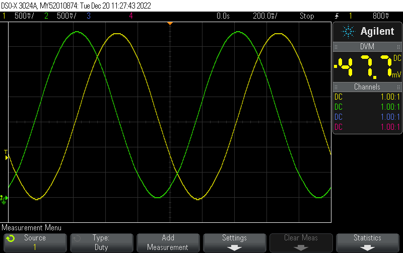
The output, filtered by a 4th order Salley-Key filter each (using the LM324) looks like this:

Posted by Uli Köhler in Analog, Arduino, Electronics, ESP8266/ESP32, PlatformIO

How to generate PWM output representing a sine wave on the ESP32 (Arduino/PlatformIO)

The following function will compute the value of a sine wave using micros() as a timebase, with adjustable frequency. It is hardcoded to expect a 12 bit resolution PWM

/**
 * @brief Calculate the PWM duty cycle (assuming 12 bits resolution) of a sine wave of
 * given frequency. micros() is used as a timebase
 * 
 * @param frequency The frequency in Hz
 * @return int the corresponding 12-bit PWM value
 */
int sinePWMValue(float frequency) {
  unsigned long currentMicros = micros(); // get the current time in microseconds

  // calculate the sine wave value for the current time
  int sineValue = 2048 + 2047 * sin(2 * PI * currentMicros / (1000000 / frequency));
  return sineValue;
}

Based on this, we can use the basic code of our previous post ESP32 minimal Arduino PWM output example (PlatformIO) to generate a 1Hz sine wave (represented by a 10kHz PWM):

#include <Arduino.h>
#include <driver/ledc.h>

void setup() {
    Serial.begin(115200);

    ledcSetup(LEDC_CHANNEL_0, 10000 /* Hz */, 12);

    ledcAttachPin(GPIO_NUM_14, LEDC_CHANNEL_0);
    ledcWrite(LEDC_CHANNEL_0, 2048); // 50%
}

/**
 * @brief Calculate the PWM duty cycle (assuming 12 bits resolution) of a sine wave of
 * given frequency. micros() is used as a timebase
 * 
 * @param frequency The frequency in Hz
 * @return int the corresponding 12-bit PWM value
 */
int sinePWMValue(float frequency) {
  unsigned long currentMicros = micros(); // get the current time in microseconds

  // calculate the sine wave value for the current time
  int sineValue = 2048 + 2047 * sin(2 * PI * currentMicros / (1000000 / frequency));
  return sineValue;
}

void loop() {
    // Example of how to change the duty cycle to 25%
    ledcWrite(LEDC_CHANNEL_0, sinePWMValue(1.0));
}


Posted by Uli Köhler in Arduino, ESP8266/ESP32, PlatformIO

ESP32 minimal Arduino PWM output example (PlatformIO)

#include <Arduino.h>
#include <driver/ledc.h>

void setup() {
    Serial.begin(115200);

    ledcSetup(LEDC_CHANNEL_0, 10000 /* Hz */, 12);

    ledcAttachPin(GPIO_NUM_14, LEDC_CHANNEL_0);
    ledcWrite(LEDC_CHANNEL_0, 2048); // 50%
}

void loop() {
    // Example of how to change the duty cycle to 25%
    ledcWrite(LEDC_CHANNEL_0, 1024);
}


Posted by Uli Köhler in Arduino, ESP8266/ESP32, PlatformIO

ESP32 minimal LEDC PWM configuration example on PlatformIO/Arduino using ESP-IDF LEDC API

This example configures the LEDC PWM timer at 10 kHz with 12 bit resolution, outputting a 50% duty cycle PWM on IO14. This code uses the ESP-IDF API directly in order to configure the PWM

#include <Arduino.h>
#include <driver/ledc.h>

void setup() {
    Serial.begin(115200);

    ledc_timer_config_t ledc_timer = {
        .speed_mode       = LEDC_HIGH_SPEED_MODE,
        .duty_resolution  = LEDC_TIMER_12_BIT,
        .timer_num        = LEDC_TIMER_0,
        .freq_hz          = 10000,
        .clk_cfg          = LEDC_AUTO_CLK
    };
    ESP_ERROR_CHECK(ledc_timer_config(&ledc_timer));

    ledc_channel_config_t ledc_channel = {
        .gpio_num       = GPIO_NUM_14,
        .speed_mode     = LEDC_HIGH_SPEED_MODE,
        .channel        = LEDC_CHANNEL_0,
        .intr_type      = LEDC_INTR_DISABLE,
        .timer_sel      = LEDC_TIMER_0,
        .duty           = 2048, // Set duty to 50%
        .hpoint         = 0
    };
    ESP_ERROR_CHECK(ledc_channel_config(&ledc_channel));
}

void loop() {
}


Posted by Uli Köhler in Arduino, ESP8266/ESP32, PlatformIO

Where to find box header footprints in KiCAD?

You can find all box headers in the Connector_IDC library in KiCAD. This library is from the standard set of KiCAD libraries, hence you don’t need to install it manually.

Posted by Uli Köhler in KiCAD