This Arduino/PlatformIO firmware outputs 50% duty cycle PWM at different frequencies on multiple pins using the LEDC PWM driver, utilizing all four timers:
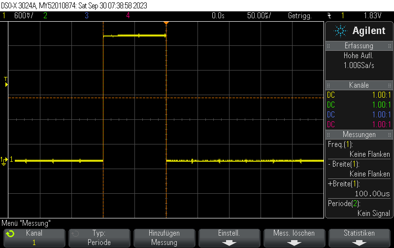
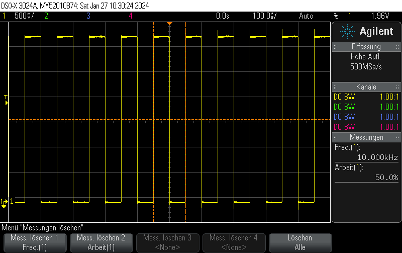
- 10 kHz on GPIO10
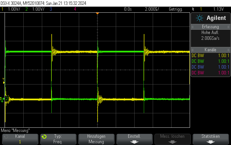
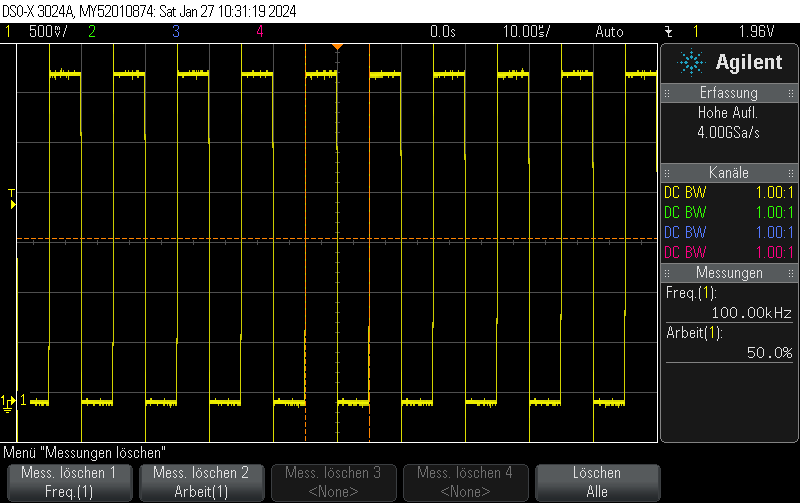
- 100 kHz on GPIO11
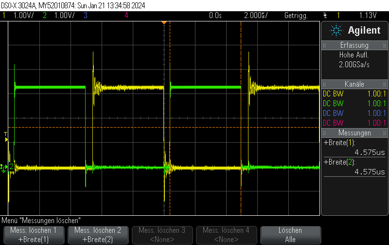
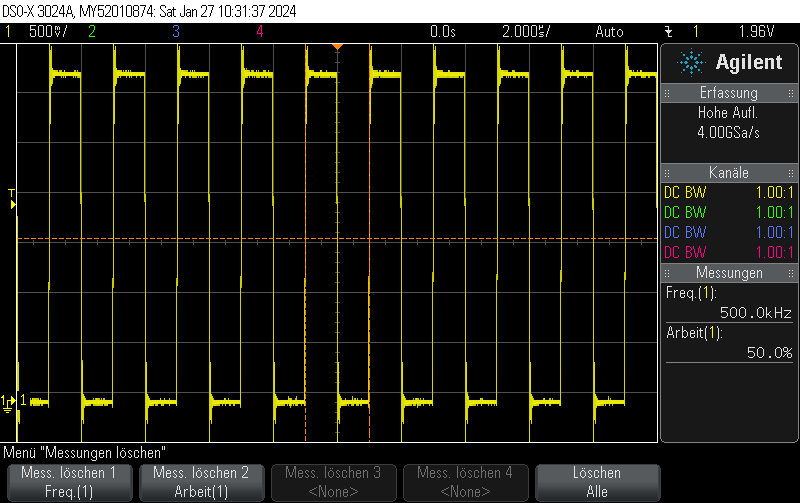
- 500 kHz on GPIO12
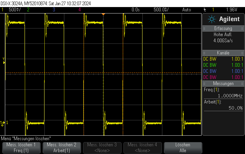
- 1 MHz on GPIO13
#include <Arduino.h>
#include <driver/ledc.h>

void setup() {

  ledc_timer_config_t ledc_timer1 = {
      .speed_mode       = LEDC_LOW_SPEED_MODE,
      .duty_resolution  = LEDC_TIMER_1_BIT,
      .timer_num        = LEDC_TIMER_0,
      .freq_hz          = 10000,
      .clk_cfg          = LEDC_AUTO_CLK
  };
  ESP_ERROR_CHECK(ledc_timer_config(&ledc_timer1));

  ledc_timer_config_t ledc_timer2 = {
      .speed_mode       = LEDC_LOW_SPEED_MODE,
      .duty_resolution  = LEDC_TIMER_1_BIT,
      .timer_num        = LEDC_TIMER_1,
      .freq_hz          = 100000,
      .clk_cfg          = LEDC_AUTO_CLK
  };
  ESP_ERROR_CHECK(ledc_timer_config(&ledc_timer2));

  ledc_timer_config_t ledc_timer3 = {
      .speed_mode       = LEDC_LOW_SPEED_MODE,
      .duty_resolution  = LEDC_TIMER_1_BIT,
      .timer_num        = LEDC_TIMER_2,
      .freq_hz          = 500000,
      .clk_cfg          = LEDC_AUTO_CLK
  };
  ESP_ERROR_CHECK(ledc_timer_config(&ledc_timer3));

  ledc_timer_config_t ledc_timer4 = {
      .speed_mode       = LEDC_LOW_SPEED_MODE,
      .duty_resolution  = LEDC_TIMER_1_BIT,
      .timer_num        = LEDC_TIMER_3,
      .freq_hz          = 1000000,
      .clk_cfg          = LEDC_AUTO_CLK
  };
  ESP_ERROR_CHECK(ledc_timer_config(&ledc_timer4));


  /**
   * @brief Configure LEDC output channels
   */

  ledc_channel_config_t ledc1 = {
      .gpio_num       = GPIO_NUM_10,
      .speed_mode     = LEDC_LOW_SPEED_MODE,
      .channel        = LEDC_CHANNEL_0,
      .intr_type      = LEDC_INTR_DISABLE,
      .timer_sel      = LEDC_TIMER_0,
      .duty           = 1, // Set duty to 50%
      .hpoint         = 0
  };
  ESP_ERROR_CHECK(ledc_channel_config(&ledc1));

  ledc_channel_config_t ledc2 = {
      .gpio_num       = GPIO_NUM_11,
      .speed_mode     = LEDC_LOW_SPEED_MODE,
      .channel        = LEDC_CHANNEL_1,
      .intr_type      = LEDC_INTR_DISABLE,
      .timer_sel      = LEDC_TIMER_1,
      .duty           = 1, // Set duty to 50%
      .hpoint         = 0
  };
  ESP_ERROR_CHECK(ledc_channel_config(&ledc2));

  ledc_channel_config_t ledc3 = {
      .gpio_num       = GPIO_NUM_12,
      .speed_mode     = LEDC_LOW_SPEED_MODE,
      .channel        = LEDC_CHANNEL_2,
      .intr_type      = LEDC_INTR_DISABLE,
      .timer_sel      = LEDC_TIMER_2,
      .duty           = 1, // Set duty to 50%
      .hpoint         = 0
  };
  ESP_ERROR_CHECK(ledc_channel_config(&ledc3));

  ledc_channel_config_t ledc4 = {
      .gpio_num       = GPIO_NUM_13,
      .speed_mode     = LEDC_LOW_SPEED_MODE,
      .channel        = LEDC_CHANNEL_3,
      .intr_type      = LEDC_INTR_DISABLE,
      .timer_sel      = LEDC_TIMER_3,
      .duty           = 1, // Set duty to 50%
      .hpoint         = 0
  };
  ESP_ERROR_CHECK(ledc_channel_config(&ledc4));

}

void loop() {
  // Nothing to do here
  delay(1000);
}
GPIO10
GPIO11
GPIO12
GPIO13