Compliance

Diagnosing I2C issues using an oscilloscope: Slow rising edge, fast falling edge

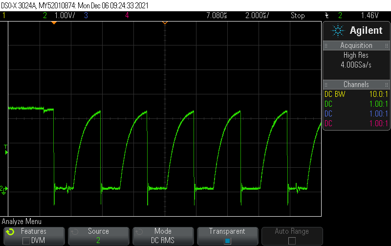
If your I2C clock and/or data signal look like this:

in other words, if the rising edge is very slow and not sharp compared to the you are facing an issue with a pull-up resistor which is too large. A good point to start is to use a pull-up resistor 1/4 the value of the pull-up currently installed on your board. If you don’t have any pull-up on your board, start with a 2.2 kOhm pull-up resistor.

As a hotfix, you can operate I2C at slower speed like 100 kHz or even slower (like 10 kHz). This will temporarily fix the issue and depending on your application there might not be any need to go faster than that.

Posted by Uli Köhler in Compliance, Electronics, Embedded

How should the SPI SCLK look on the oscilloscope?

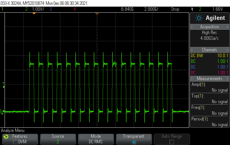
SPI is typically used at 1-20MHz clock frequency. Start with setting the oscilloscope to 2 microseconds per division and 2V per division. Hence, set your scope. Set the trigger to edge mode to trigger at half the supply voltage (e.g. 1.65V for 3.3V supply voltage).The following example is SPI running at 1 MHz on a supply of 3.3V:

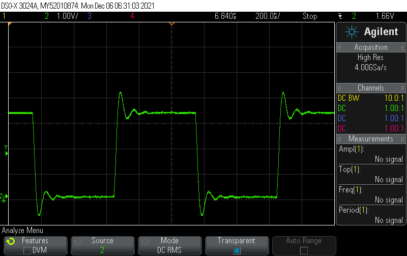
Always start by measuring SCLK, to verify both a valid signal clock and your measurement setup. The signal should always look like this:

The first aspect to verify here is that the SCLK should be mostly symmetric (50% duty cycle) and running continously throughout each SPI data transfer. The frequency should typically not change during a single SPI transfer.

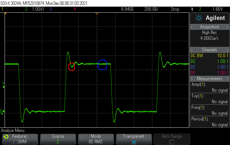
SPI tolerates a significant amount of overshoot. In case you have signal integrity issues, you can typically just reduce the clock speed. In order to have a closer look on the signal integrity aspects, zoom in so you see just one clock cycle.


The amount of overshoot you see in our example is totally fine. What you should look for here is that both the rising and falling edge should be reasonably sharp and the 0 and 1 bits should be clearly visible.

Regarding overshoot/undershoot, a good rule of thumb is that during the 1 bit, the voltage should never be less than 0.8 times the steady-state voltage during the one bit (see below for red and blue markers):

Similarly, during the 0 bit, the voltage should never be less than 0.2 times the steady-state voltage during the one bit

Note that not only does your PCB affect the signal integrity – your measurement setup (oscilloscope & probe) affects them to some extent as well.

Posted by Uli Köhler in Compliance, Electronics, Embedded

What 1500pF 1kV capacitor should you use for Ethernet termination?

Nowadays you can use cheap ceramic capacitors for Ethernet termination. While they are not self-healing like foil capacitors, they work fine for all but the most demanding applications. Also, it’s typically much cheaper to assemble SMD capacitors as opposed to through-hole foil types since the SMD types can be more easily picked & placed by machines.

I recommend to use the Yageo CC1206KKX7RCBB152 because it’s cheap (0,10€ @100pcs) and readily available at every major distributor.

Furthermore, it has a X7R ceramic, meaning that its capacitance doesn’t change too much with temperatur (not as much as, for example, Y5V ceramics). Note that X5R and X7R types have a capacity that depends on the voltage being applied, so if you have an application that is really sensitive to RF noise, keep in mind that if a significant DC voltage is applied to the capacitor, its capacitance will drop by up to tens of percents – leading to impromper Ethernet termination and hence more EMI.

Additionally, keep in mind that ceramic capacitors are somewhat susceptiple to mechanical flexing of the PCB. This is especially the case if you have a very thin (or even rigid-flex) PCB, or if high mechanical loads (either static loads or vibrations) are applied directly to your PCB. In that case, consider buying e.g. a slightly more expensive, “flexible termination” type capacitor.

Posted by Uli Köhler in Compliance, Electronics, EMI

Why do medical devices need 2xMOPP?

Also see: Does 2xMOOP / 2xMOPP require two separate converters / layers of isolation?

For medical devices the IEC60601 norm specifies more stringent requirements for electrical safety like the 2xMOPP requirement (MOPP = Means of Patient Protection). Many developers wonder why the requirements are different to other types of devices like consumer devices.

  • It is assumed that patients might already have impaired health and hence any additional damage caused by e.g. a malfunctioning medical device might have greater consequences than in healthy patients.
    • For example, assume that a patient with a severe infection receives a light  electric shock from a malfunctioning infrared thermometer. While the electric shock is unrelated to the original injury of the patient (i.e. the infection), having to treat both issues might be much harder than just treating the infection: For example, the infection might spread to the body part where the electric shock occured, or the additional inflammation due to the electric shock might contribute to the deteriorating health of the patient
  • Additionally, if a patient receives e.g. an electric shock from a medical device, many patients will not trust medical devices – and potentially even the entire medical system – any more, resulting in less capability of treating those patients.
    • Imagine if you would receive a small, unpleasant (but not in any way dangerous) shock every time you use a thermometer to measure fever. Most people would refrain from measuring their temperature when they are ill in order to avoid the impleasant shock. This will lead to many patients being diagnosed at a later stage of their disease which would in turn impede the treatment.
  • Furthermore, it is assumed that the medical device will be used under circumstances like pandemics, where any additional injury will unneccessarily consume medical resources such as hospital beds and keep medical personnel from treating potentially more serious injuries.
Posted by Uli Köhler in Compliance, Electronics, Medical devices

What is a SELV power supply?

SELV means Safety extra low voltage.

This means that

  • the voltage at the output of the power supply is so low that is isn’t considered a safety risk (less than 60V DC or 35VAC).
  • the secondary side is isolated from the primary side by double or reinforced insulation, so that the output terminals can’t become electrically dangerous by short-circuiting to the primary side (which is connected e.g. to 230VAC mains)
  • the secondary side is isolated from earth so if there are faults in other devices connected to the same earth conductor, the output of the SELV power supply can’t get unsafe.

What does 60V DC mean in practice?

Typically the 60V value is defined as ripple-free DC. This means that the peak value of the waveform is not more than 10% higher than the maximum allowed voltage, e.g. it must not be more than 70V for a 60V system.

For 35VAC, the peak value has to be considered.

The values are typically measured across a 50kΩ resistance, refer e.g. to IEC61347-1 Annex A (the standard for safety of power supply for lighting purposes).

What does double or reinforced insulation mean?

This is an insulation that is so thick that even under extreme, abnormal conditions (like power surges due to lightning) it will not cause a discharge through the isolation.

This can be achieved by either using double insulation, which is just two layers of basic (non-reinforced) insulation, or using a much thicker type of insulation, reinforced isolation. In almost all cases, using reinforced isolation is more economical than using double insulation.

While this depends on the material, typically 0.4mm of insulating plastic foil is sufficient to count as reinforced insulation, however most standards require the insulator in use to be tested for its safety.

Can the primary side be connected to Earth?

Yes, the primary side may or may not be connected to Earth (as a third conductor). As long as the secondary side is not connected to earth, this does not affect the SELV rating, however note that this might have other implications since a power supply with primary connected to Earth is a Class I power supply whereas a power supply without any Earth connection is a Class II power supply.

There are many differences in how Class I and Class II power supplies are treated, so you need to check your applicable standards for details.
Posted by Uli Köhler in Compliance, Electronics

What is a transformer construction according to clause 26.2.4.1 of IEC 61558-1?

In transformer specifications or tests, you will often find sentences like

Construction according to clause 26.2.4.1 of IEC 61558-1

This clause refers to hermetically sealed construction by impregnation potting (even if only parts of the transformer are potted), i.e. the transformer is (partially) filled with epoxy or similar potting materials in order to prevent moisture or dust from influencing its performance.

This usually means:

  • the transformer can be smaller since the safety regulations (IEC61558-1) requires  less creepage distances compared to non-potted transformers
  • the transformer manufacturer has to perform additional tests according to IEC61558-1 (compared to non-potted transformers) to prove that the potting material provides sufficient isolation
  • the transformer is typically more expensive than an equivalent non-potted transformer since it needs to be potted in the factory and additional safety tests need to be performed on transformer specimens.

Also see What is a transformer construction according to clause 19.12.3 of IEC 61558-1?

Posted by Uli Köhler in Compliance, Electronics

What is a transformer construction according to clause 19.12.3 of IEC 61558-1?

In transformer specifications or tests, you will often find sentences like

Construction according to clause 19.12.3 of IEC 61558-1

This clause refers to isolated winding wire construction, i.e. a way of making a transformer where the isolation of the winding wires themselves is the only isolation.

This usually means:

  • that the winding wires will have multiple layers of isolation (usually two or three to satisfy safety requirements from IEC61558-1)
  • that there is no additional isolation foil since the isolation of the wound wires is sufficient to fulfil the safety requirements
  • that manufacturer will need to perform additional safety tests for each and every transformer (100% production test) to prove that the transformer is safe.

Also see What is a transformer construction according to clause 26.2.4.1 of IEC 61558-1?

Posted by Uli Köhler in Compliance, Electronics

X1/X2/Y1/Y2/Y4 impulse withstand rating voltage calculator (IEC 60384-14)

IEC 60384-14 specifies that X1/X2-rated capacitors shall be tested to withstand an impulse voltage of 4 kV (X1), 2.5 kV (X2, Y4), 8 kV (Y1) or 5 kV (Y2).

However these values only apply for a capacitance \leq 1 μF (except for Y1/Y4 capacitors). Use this calculator for X1/X2/Y2 capacitances > 1 μF!

TechOverflow calculators:
You can enter values with SI suffixes like 12.2m (equivalent to 0.012) or 14k (14000) or 32u (0.000032).
The results are calculated while you type and shown directly below the calculator, so there is no need to press return or click on a Calculate button. Just make sure that all inputs are green by entering valid values.

F

Formula:

Up = \frac{Up_{\leq 1 μF}}{\Large\sqrt{\frac{C}{1\,000\,000\frac{μF}{F}}}}

where:

  • Up is the impulse withstand voltage rating
  • C is the capacitance in Farads
  • Up_{\leq 1 μF} is the voltage rating for that capacitor class with a capacitance of \leq 1 μF:
    • For X1-class: 4 kV
    • For X2-class: 2.5 kV
    • Y1-class impulse withstand voltage is always 8 kV no matter what capacitance
    • For Y2-class: 5 kV
    • Y4-class impulse withstand voltage is always 2.5 kV no matter what capacitance

Why is the impulse withstand voltage lower for larger capacitors?

The rationale behind the derating of the impulse withstand voltage is that larger capacitances will have sufficient capacitance so that a given overvoltage doesn’t cause a large voltage spike in the capacitor.

The formula (see above) is chosen so that the energy in the capacitor:

E = \frac{1}{2}\cdot{}C\cdot{}U_p^2

is kept constant (i.e. at the same value as for a equivalent capacitor of 1 μF).

Posted by Uli Köhler in Calculators, Compliance, Electronics