3D printing

What does the M105 / M155 line format (T:20.38 /185.00 @:127) mean?

The M105 G-Code for printer firmwares like Marlin prints lines such as

T:20.38 /185.00 @:127

The RepRap wiki has extensive documentation about those lines. Here are the most important ones

  • T:actual /setpoint Temperature of the hotend in °C
  • T0:actual /setpoint Temperature of the first hotend in °C (only if you have multiple hotends)
  • T1:actual /setpoint Temperature of the second hotend in °C (only if you have multiple hotends)
  • B:actual /setpoint Temperature of the heated bed in °C
  • C:actual /setpoint Temperature of the printer case in °C
  • @:value : Current PWM output value of the hotend. Typically, 8-bit PWM is used, so 255 is full-scale.
  • B@:value : Current PWM output value of the bed. Typically, 8-bit PWM is used, so 255 is full-scale.
Posted by Uli Köhler in 3D printing

OctoPrint systemd service file for autostarting OctoPrint

After you have installed OctoPrint using

sudo pip3 install OctoPrint

you can create /etc/systemd/system/octoprint.service with the following content (depending on your setup, you might need to replace the user & group pi by the name of the user that should run OctoPrint):

[Unit]
Description=octoprint

[Service]
ExecStart=/usr/local/bin/octoprint serve
WorkingDirectory=/data
Restart=always
User=pi
Group=pi

[Install]
WantedBy=multi-user.target

After creating the file, enable autostart & start the service using

sudo systemctl enable --now octoprint


Posted by Uli Köhler in 3D printing, systemd

PySerial minimal example: Copy data received from serial port to stdout

This example does not send data to the serial port but only copies data received from the serial port to stdout. Newlines received from the serial port are preserved.

#!/usr/bin/env python3
import serial
ser = serial.Serial("/dev/ttyUSB0", baudrate=115200)

try:
    while True:
        response = ser.read()
        if response:
            print(response.decode("iso-8859-1"), end="")
finally:
    ser.close()

By using iso-8859-1   decoding, we ensure that even binary bytes are decoded in some way and do not cause an exception.

Posted by Uli Köhler in 3D printing, Embedded, Python

How to flash Marlin 2.x to BTT SKR 1.4 using PlatformIO

The best way to flash Marlin via PlatformIO onto the LPC1768 MCU on a BTT SKR v1.4 board is to insert an SD card into it, connect the computer via USB and use the mbed as upload_protocol.

In order to do this, edit ini/lpc176x.ini from within Visual Studio Code and add the following new code to [env:LPC1768]:

upload_protocol = mbed
upload_port=/media/uli/A87B-A154/

with upload_port being the directory where the SD card is mounted (while you can do this using an SD card reader, it is so much easier by just connecting the BTT SKR v1.4 via USB directly to your computer, allowing both serial port and SD card access at the same time).

Full example of the [env:LPC1768] section:

[env:LPC1768]
platform = ${common_LPC.platform}
extends  = common_LPC
board    = nxp_lpc1768
upload_protocol = mbed
upload_port=/media/uli/A87B-A154/

In the PlatformIO menu, choose LPC1768/Upload. There is no special configuration for the BTT SKR v1.4 but of course you need to configure Configuration.h etc correctly – see https://www.makenprint.uk/3d-printing/3d-printing-guides/skr-v1-4-configuration-h-marlin-2-setup-part-2/

After uploading, press the reset button on the Board to apply the firmware update. You can use picocom to connect to your printer, see How to connect to your 3D printer using picocom, e.g.:

picocom -b 115200 /dev/ttyACM0 --imap lfcrlf --ech

Enter M115 to check if you have correctly updated the fiwa

You might need to manually re-mount the SD card using your file manager after a firmware update in order to enabled PlaformIO doing another update.

Posted by Uli Köhler in 3D printing, Embedded, PlatformIO

How to enable OctoPi WiFi connection on boot

First, install OctoPi to the SD card – for example, using rpi-imagerHow to install OctoPi using rpi-imager

Open the boot partition on the OctoPi SD card and create a file wpa_supplicant.conf there, with the following content:

country=de
update_config=1
ctrl_interface=/var/run/wpa_supplicant

network={   
   scan_ssid=1
   ssid="MyWifi"  
   psk="abc123abc"
}

Always set the correct country code at the top ! If you don’t set it correctly, it won’t work!

Set ssid to the name of the wireless network.

Set psk to the wifi password.

Posted by Uli Köhler in 3D printing, Raspberry Pi

How to install OctoPi using rpi-imager

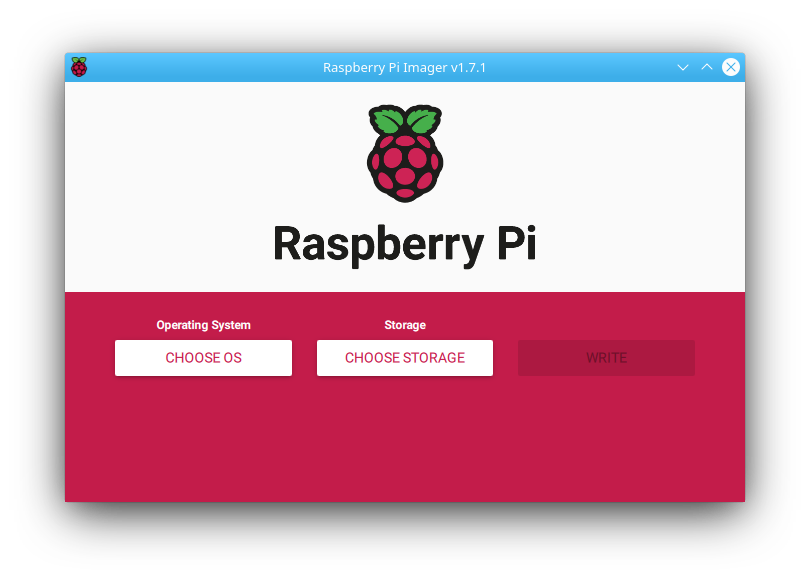
First open rpi-imager:

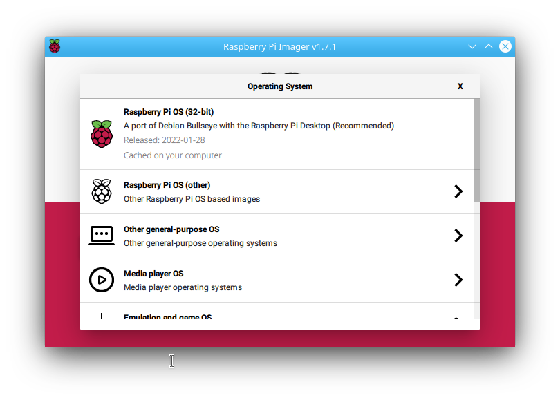
then select Choose OS

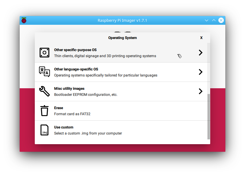
Sroll down to Other specific-purpose OS (do not click on Other general-purpose OS, even though it sounds similar!)

Click on Other specific-purpose OS:

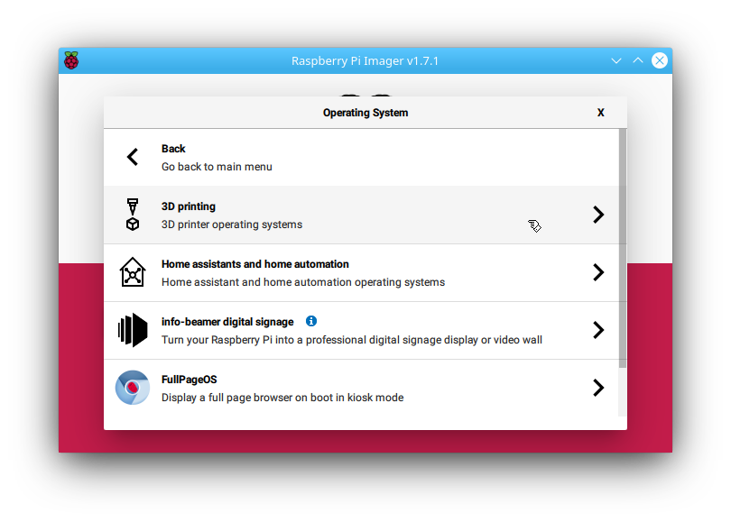
Now click on 3D printing:

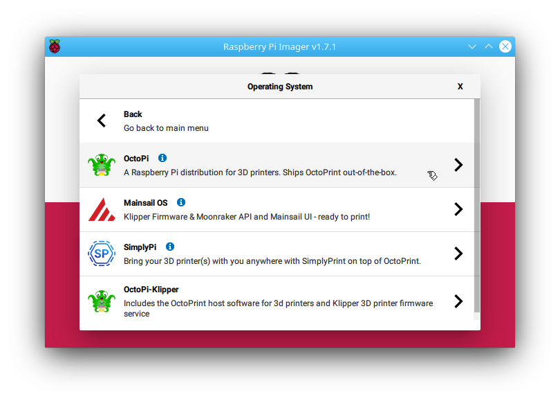
Click on OctoPi:

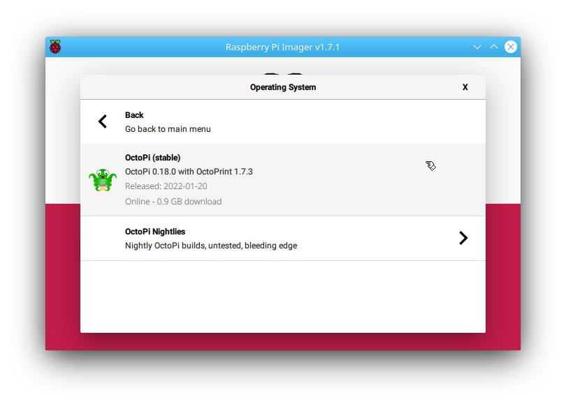
Now click on OctoPi (stable):

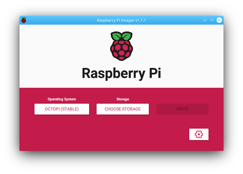
Now click on Choose Storage to select the SD card you want to write the image to:

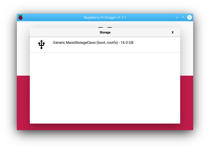
Click on the correct device to select it – double check to make sure you have selected the correct device !

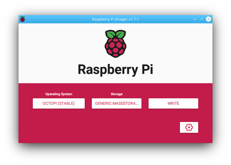
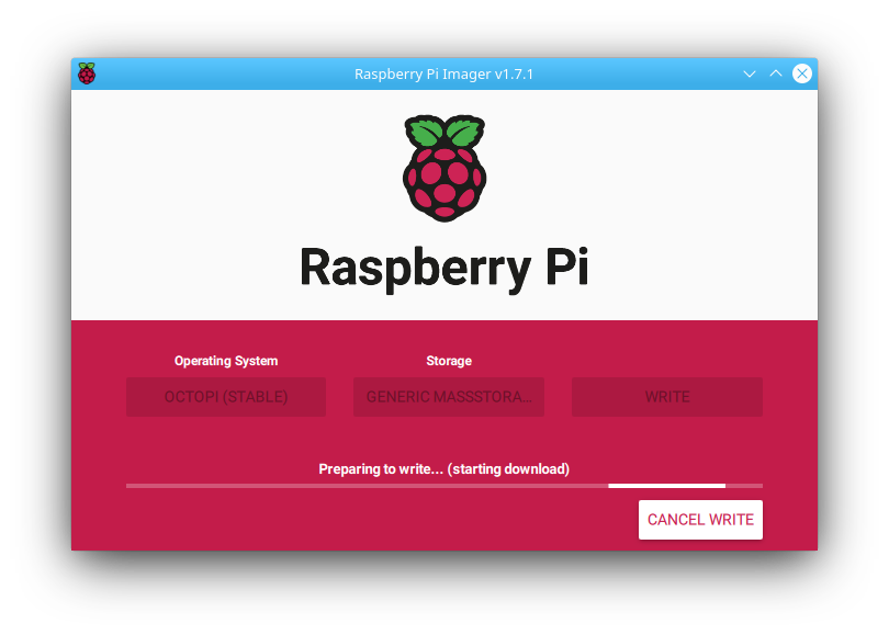
Now click Write to download the image and write it to the SD card:

and now grab a coffee since it will take a couple of minutes to write:

Posted by Uli Köhler in 3D printing, Raspberry Pi

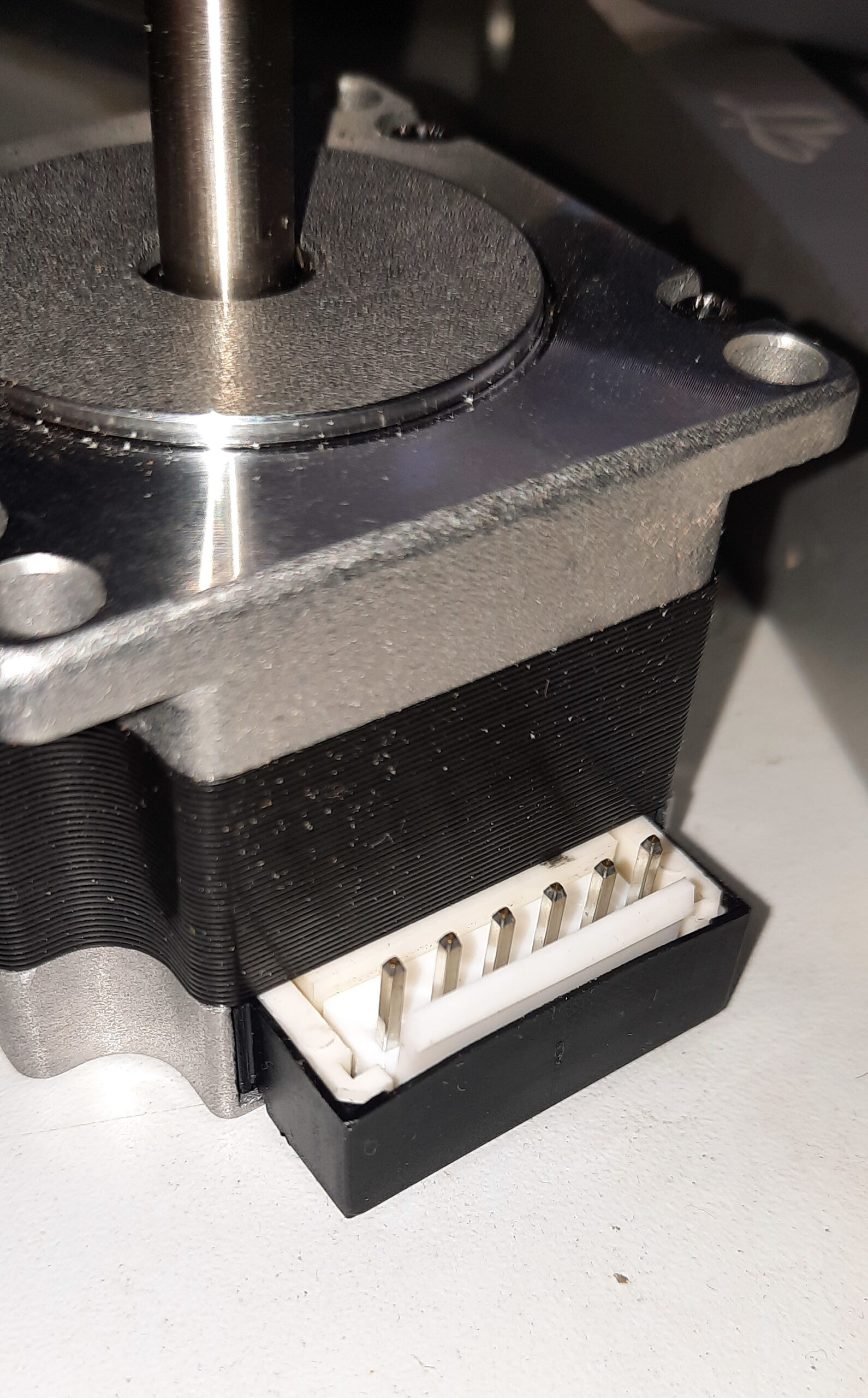
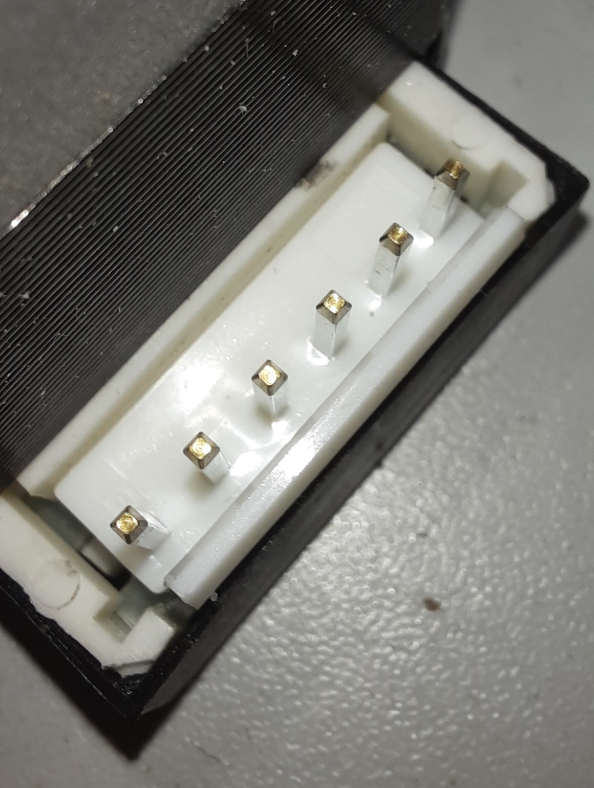
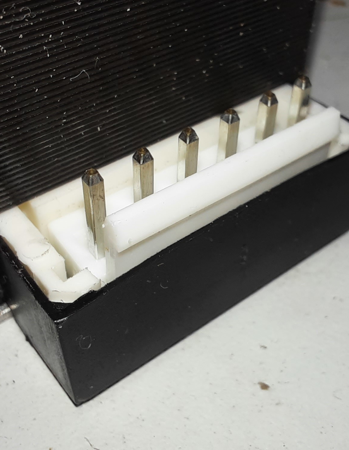
What 6-pin connector do NEMA23 stepper motors use?

There are multiple different types of connectors for NEMA23 stepper motors. This is one of them.

A typical connector for NEMA23 stepper motors such as the Nanotec SCA5618X2804-A is the JST B6P-VH (part number of the male connector on the motor, source: NanoTec datasheet).

The corresponding mating connector is the JST VHR-6N, the series of connectors is being called JST VH. The pitch is 3.96mm.

The crimp contacts part numbers are (source: datasheet):

  • SVH-21T-P1.1 for 0.33mm² to 0.88mm²
  • SVH-41T-P1.1 for 0.5mm² to 1.25mm²

Posted by Uli Köhler in 3D printing

How to cool down Extruder using G-Code (Marlin)

Use M104 to cool down the extruder:

M104S0 ; Cooldown hotend


Posted by Uli Köhler in 3D printing

How to check a stepper motor for open/short circuit?

In order to correctly check a stepper motor for a hard short circuit, you need an LCR meter. If you only have an multimeter, skip the winding inductance check.

Measuring the phase resistance

First, check the resistance of each phase winding (pair A and pair B). The resistance should be between 0.5 Ω and 5 Ω, but note that it is also influenced by your multimeter probes and the contact resistance from the probe to the pin. If possible, compare the measurement to the datasheet of your stepper motor or to the datasheet of your motor or a good motor of the same model. If the datasheet lists 1.5 Ω, I would accept anything from 1.0 Ω to 2.0 Ω. If you see an infinite resistance (typically indicated by OL [overload] on your multimeter), either you measured the wrong pins or your probes do not electrically contact the pins – or your motor has an open winding (no contact). Re-measure multiple time, trying to contact the pin on different points on the surface to confirm. Also check if your multimeter displays a sensible value if you short the multimeter probes.
If you see a resistance that is way too low (e.g. 0.2 Ω for a nominal 1.5 Ω motor), your winding is shorted. This is typically not caused by a bad contact from the probes to the pin, but re-measure a few times just to confirm.

Now measure the resistance from one of the phase A pins to one of the phase B pins. The resistance should typically be OL (overload – i.e. a resistance so high the multimeter can’t measure it), but at least 5.0 MΩ. If it is any less, this indicates that the phases are shorted to each other. Be sure that you measured the correct pins.

Measuring the phase inductance

Now, Check the inductance of each phase winding (pair A and pair B). The inductance should be a couple of mH, but never below 100uH. A lower inductance indicates an winding that is shorted internally. If possible, compare with the datasheet of your stepper motor or see What phase inductivity value should my stepper motor have? for more details on this topic.

Now check, using the resistance mode of your LCR meter, check if any phase wiring has. Typically the resistance between one phase winding and the other

If you don’t know which pins of the connector belong to which phase winding, the two pins of each pair should have an inductance that is within ±30% of each another at maximum.

Posted by Uli Köhler in 3D printing, Electronics

How to fix Marlin random driver error detected coil short circuit crash (Trinamic TMC)

Problem:

When using Trinamic drivers with the Marlin 3D printer firmware, you might occasionally experience errors like

Send: N4193 G1 X12.345 Y34.567 E122.15252
Recv: 
Recv: E driver error detected: 0x10136000
Recv: coil short circuit
Recv: 		X	Y	Z	E
Recv: Enabled		true	true	true	true
Recv: Set current	2000	2000	2000	1000
Recv: RMS current	1999	1999	1999	990
Recv: MAX current	2819	2819	2819	1396
Recv: Run current	31/31	31/31	31/31	19/31
Recv: Hold current	15/31	15/31	15/31	9/31
Recv: Global scaler	167/256	167/256	167/256	133/256
Recv: CS actual	31/31	31/31	22/31	19/31
Recv: PWM scale	196716	33095745	65576	33488924
Recv: vsense
Recv: stealthChop	true	true	true	true
Recv: msteps		128	128	128	128
Recv: interp		true	true	true	true
Recv: tstep		171	678	max	1580
Recv: PWM thresh.	24	24	411	13
Recv: [mm/s]		102	102	3	41
Recv: OT prewarn	false	false	false	false
Recv: triggered
Recv:  OTP		false	false	false	false
Recv: off time	4	4	4	4
Recv: blank time	24	24	24	24
Recv: hysteresis
Recv:  -end		2	2	2	2
Recv:  -start		1	1	1	1
Recv: Stallguard thrs	0	0	0	0
Recv: uStep count	62	32	227	497
Recv: DRVSTATUS	X	Y	Z	E
Recv: sg_result	0	0	395	0
Recv: stallguard
Recv: fsactive
Recv: stst		*	*		*
Recv: olb
Recv: ola
Recv: s2gb					*
Recv: s2ga
Recv: otpw
Recv: ot
Recv: Driver registers:
Recv: 		X	0x00:1F:40:00
Recv: 		Y	0x00:1F:40:00
Recv: 		Z	0x80:16:41:8B
Recv: 		E	0x10:13:60:00
Recv: 
Recv: 
Recv: echo:Driver error
Recv: Error:Printer halted. kill() called!
Changing monitoring state from "Printing" to "Error"

Solution:

If the error always occurs at the start of each print, be sure to check your stepper motor setup for actual shorts! Measure the inducitivity using an LCR meter to be sure, it should be around the rated value for your motor! See this post for information about typical stepper motor inductivity.

If the error occurs occasionally, it is recommended in the datasheet that you use more conservative short detection settings.

You need to make the change this in Marlin/src/module/stepper/trinamic.cpp.

Go to the section for the driver type you are using. In my example, this would be

#if HAS_DRIVER(TMC5160)
// ...
void tmc_init(/* ... */) {
   // NOTE: tmc_init() is the function we need to insert code in!
}
#endif

Now insert, just before the TERN(HYBRID_THRESHOLD, /* ... */) line (if such a line does not exist, insert at the end of the function:

// Set more conservative short detection settings
st.shortfilter(3); // 3us SHORT filter
st.s2vs_level(15); // Lowest sensitivity short to supply voltage protection
st.s2g_level(15); // Lowest sensitivity short to ground protection
st.shortdelay(1); // 1.5us instead of 0.75us short delay

These are the most conservative settings possible using this setup.

Now retry your print.

In case this still doesn’t help, you can disable short protection entirely. Note that short protection exists to prevent damage to your stepper motor, your mainboard and your cabling, so you should only disable it if there is no other choice!

In order to disable short protection entirely, insert this code block instead of the conservative setting code block from above:

// Disable short protection entirely
st.diss2g(true);
st.diss2vs(true);

Tested with Marlin version 2.0.9.1
Posted by Uli Köhler in 3D printing, Embedded

What phase inductivity value should my stepper motor have?

Stepper motor phase inductivity varies widely. Even for a given size of stepper motor, such as NEMA17 with a length of 38mm, you can buy widely varying inductivity values even from the same manufacturer:

Both of these have the same holding torque of 80NcmInductivity is not an indicator of motor power!

As a general rule, remember:

  • NEMA17 steppers tend to be in the 1mH to 50mH range.
  • NEMA23 steppers tend to be in the 250μH to 25mH range

If you are checking your motor for a shorted winding, if the inductance is below 100μH, you can be pretty sure that the stepper motor is defective.

Posted by Uli Köhler in 3D printing, Electronics

Where to find 10x10x10mm (1cm) solid test cube STL?

Test cubes are a useful tool for testing a 3D printer.

You can download a simple 10x10x10mm (1cm x 1cm x 1cm) test cube on Thingiverse.

Posted by Uli Köhler in 3D printing

How to install OctoScreen plugin for OctoPrint

OctoScreen provides a plugin that you can use within OctoPrint to configure the UI. You can find it on GitHub here, but you can simply install it using the OctoPrint plugin manager using the following URL:

https://github.com/Z-Bolt/OctoPrint-Z-Bolt-OctoScreen/archive/master.zip


Posted by Uli Köhler in 3D printing

How to change OctoScreen minimum extrusion temperature

Problem:

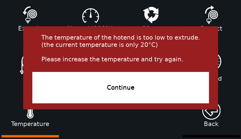
When trying to extrude low-temperature filaments using OctoScreen, you will see this error message:

The temperature of the hotend is too low to extrude. Please increase the temperature and try again

By default, OctoScreen has a minimum extrusion temperature of 150°C which is fine for PLA, but  for some low temperature materials you need to change the hardcoded value.

Note that setting you minimum extrusion temperature too low might damage or even destroy your extruder, if the material is not properly melted. So take caution in setting the correct value here.

Solution:

Open utils/tools.go and edit this line:

const MIN_HOTEND_TEMPERATURE = 150

Just set your desired temperature and then recompile (see the OctoScreen README on how to do that)

Note that often the firmware (like Marlin) has a separate cold extrusion prevention limit, so you need to change the limit in both OctoScreen and the firmware. For Marlin, see How to disable Marlin cold extrusion prevention via G-Code.


Posted by Uli Köhler in 3D printing, Embedded, Raspberry Pi

How to auto-reset Marlin after Kill

Under certain critical circumstances like thermal runaway protection, Marlin entered a killed state. You typically need to hard-reset the mainboard after entering that state. However, in environments where physical access to the machine, hard-resetting Marlin is not possible, so you might need to implement.

Note that diagnosing & fixing the underlying issue that caused the reset is extremely important and ignoring it might lead to further issues, up to a fire hazard or the destruction of the printer. So be sure to know what you are doing before just.

The following guide was tested with Marlin 2.0.9.1. It should work with most Marlin 2.x versions with minor adjustments.

First, note that as an alternative to hard-resetting the mainboard there is the SOFT_RESET_ON_KILL option which allows you to trigger a soft reset out of kill mode using a button connected to a pin. We won’t delve into more detail on this, since it doesn’t really change the requirement for physical access to the printer.

Open Marlin/src/MarlinCore.cpp and find the minkill(bool) function.

At the end, this function contains a preprocessor-controlled branch of the following structure:

#if EITHER(HAS_KILL, SOFT_RESET_ON_KILL)
  // Branch 1 ...
#else
  // Branch 2 ...
#endif

We will replace this entire branch by these lines:

// Wait for 5 seconds for controller to catch up
for (int i = 5000; i--;) { DELAY_US(1000); watchdog_refresh(); } // 5000*1ms = 3s
// Auto-reset after kill
HAL_reboot();

I prefer to insert the 5-second delay into the reboot logic so no superordinate controller (like a Raspberry Pi running OctoPrint) can miss that the Marlin board has been killed. Although most controllers should be able to detect the killed state from the G-Code, this 5-second delay will simulate the default behaviour of not resetting at all after the killed state has been reached. However note that in case you absolutely need to reset ASAP after the kill state has been reached, it’s typically safe to omit the wait loop.

Posted by Uli Köhler in 3D printing, Embedded

Implementing STM32 DFU bootloader firmware upgrade in Marlin using M997

Marlin implements the M997 command which is intended to switch the mainboard into a firmware upgrade mode.

All STM32 variants have an integrated (hard-coded – so no need to flash it yourself) bootloader that is notoriously difficult to active.

However, Marlin implements M997 on the STM32 as just a reboot:

void flashFirmware(const int16_t) { HAL_reboot(); }

This only works if you are using a custom bootloader on your board – however, it does not use the STM32 integrated bootloader.

The following code was tested on the STM32F446 (BigTreeTech Octopus V1) but should work on any STM32 variant. It is based on previous work by Dave Hyland on StackOverflow. Replace the default flashFirmware() function in Marlin/src/HAL/STM32/HAL.cpp

void flashFirmware(const int16_t) {
    HAL_RCC_DeInit();
    HAL_DeInit();

    __HAL_REMAPMEMORY_SYSTEMFLASH();

    // arm-none-eabi-gcc 4.9.0 does not correctly inline this
    // MSP function, so we write it out explicitly here.
    //__set_MSP(*((uint32_t*) 0x00000000));
    __ASM volatile ("movs r3, #0\nldr r3, [r3, #0]\nMSR msp, r3\n" : : : "r3", "sp");

    ((void (*)(void)) *((uint32_t*) 0x00000004))();

    // This will never be executed
    HAL_reboot();
}

Note that we left a HAL_reboot() call as a safeguard at the end, just in case the previous calls fail.

On my BigTreeTech Octopus V1 (STM32F446), by using this code, you can successfully enter the integrated DFU bootloader.

Also see our previous posts on how to use the STM32 in DFU bootloader mode:

Posted by Uli Köhler in 3D printing, C/C++, STM32

M206 Set home offset: Positive or negative coordinates? A simple rule for Marlin

When adjusting the home offset (most often the Z offset) of a 3D printer using the M206 command, many users wonder which sign to use. In other words, in order to move the nozzle 0.1mm closer to the bed, do you use M206Z0.1 or M206Z-0.1. However, there’s a simple rule:

To move the nozzle closer to the bed, use positive coordinates, e.g. M206Z0.1 to move the nozzle 0.1mm closer to the print bed.

To move the nozzle further away from the bed, use negative coordinates, e.g. M206Z-0.2 to move the nozzle 0.2mm further away from the print bed.


Posted by Uli Köhler in 3D printing

How to run single command on 3D printer using picocom

In our previous post How to connect to your 3D printer using picocom we showed how to open an interactive serial session on the command line using picocom. But you can also use picocom to run just a single command such as the M997 firmware update command:

echo "M997" | picocom -b 115200 /dev/ttyACM0 --imap lfcrlf --echo

If your USB serial device is named /dev/ttyUSB0 instead of /dev/ttyACM0 you can use this alternative version:

echo "M997" | picocom -b 115200 /dev/ttyUSB0 --imap lfcrlf --echo


Posted by Uli Köhler in 3D printing, Linux