Arduino

Measurement averaging code with fixed time windows for microcontrollers (C++)

This class performs averaging with a fixed time window (variable number of values).

From the platform, it only needs some method to get the current time. This code contains implementations for both ESP-IDF and Arduino

#pragma once
#include <optional>

// Find the correct driver
#ifdef ARDUINO
    #include <Arduino.h>
    #define TTAA_GETTIME_MILLIS millis()
#elif defined(IDF_VER) && !defined(ARDUINO)
    #include <esp_timer.h>
    #define TTAA_GETTIME_MILLIS esp_timer_get_time() / 1000
#else
    #error "Could not determine how to get the current time (Arduino or ESP-IDF)"
#endif

/**
 * @brief This class is designed to accumulate and average values over a specified time threshold.
 * 
 * The class is templated to allow accumulation of different numerical types, defaulting to float. It uses the Arduino `millis()`
 * function to track elapsed time, automatically calculating the average of accumulated values once the predefined time threshold is reached.
 * The `add()` method adds a new value to the accumulation, returning the average as a `std::optional<T>` when the threshold is reached,
 * and `std::nullopt` otherwise. The `lastAverage()` method allows retrieval of the last calculated average at any time.
 */
template<typename T = float>
class TimeThresholdAccumulatingAverager {
public:
    /**
     * Constructs a new TimeThresholdAccumulatingAverager object.
     * 
     * @param threshold The time threshold in milliseconds over which to accumulate and average values.
     */
    TimeThresholdAccumulatingAverager(unsigned long threshold) : _threshold(threshold), _startTime(TTAA_GETTIME_MILLIS), _sum(), _count() {}

    /**
     * Adds a value to the accumulator. If the time threshold has been reached, 
     * calculates and returns the average of the accumulated values since the last threshold reset.
     * Resets the accumulator for the next period if the threshold is reached.
     * 
     * The given value is not added to the current average if the threshold has been
     * exceeded. It is automatically added to the next period's average. 
     * 
     * @param value The value to add to the accumulator.
     * @return std::optional<T> The average of accumulated values if the threshold is reached, otherwise std::nullopt.
     */
    std::optional<T> add(T value) {
        unsigned long currentTime = TTAA_GETTIME_MILLIS;

        if (currentTime - _startTime >= _threshold) {
            // Time threshold exceeded. Calculcate average
            T average = _count > 0 ? _sum / static_cast<T>(_count) : 0;
            _lastCount = _count;
            // Reset sum & count to zero, but add the current value immediatey
            _sum = value;
            _count = 1;
            _startTime = currentTime;
            _lastAverage = average;
            return average;
        } else { // Time threshold not exceeded
            _sum += value;
            _count++;
            return std::nullopt;
        }

    }

    /**
     * Returns the average of the last completed accumulation period.
     * 
     * @return T The average value of the last completed period.
     */
    inline T lastAverage() const {
        return _lastAverage;
    }

    /**
     * Returns the count value of the last completed accumulation period.
     *
     * @return The last count value.
     */
    inline unsigned int lastCount() const {
        return _lastCount;
    }

private:
    unsigned long _threshold;
    unsigned long _startTime;
    T _sum;
    int _count = 0;
    T _lastAverage = 0;
    unsigned int _lastCount = 0;
};

Usage example:

#include <optional>
#include <iostream>

#include "TimeThresholdAccumulatingAverager.hpp"

int main() {
    TimeThresholdAccumulatingAverager<float> averager(1000); // 1 second threshold

    while (true) {
        float newValue = acquireValue(); // Pseudocode for acquiring a new value
        auto maybeAverage = averager.add(newValue);

        if (maybeAverage.has_value()) {
            std::cout << "Average over threshold period: " << average.value() << std::endl;
        }

        // Add a delay or wait for a real new value in a real application
        delay(10);
    }
}
 

Posted by Uli Köhler in Arduino, Embedded, ESP8266/ESP32, PlatformIO

STM32H743 Arduino PlatformIO example: Read ADC with 16 bit resolution

This example configures ADC1 to read a 16 bit analog value of PA7 using a polled loop. The serial output is available on the STLink header.

#include <Arduino.h>
#include <stm32h7xx_hal.h>

ADC_HandleTypeDef hadc1;

static void MX_GPIO_Init(void)
{
    GPIO_InitTypeDef GPIO_InitStruct = {0};

    // Enable the GPIOA clock
    __HAL_RCC_GPIOA_CLK_ENABLE();

    /**ADC1 GPIO Configuration    
    PA7     ------> ADC1_IN7 
    */
    GPIO_InitStruct.Pin = GPIO_PIN_7;
    GPIO_InitStruct.Mode = GPIO_MODE_ANALOG;
    GPIO_InitStruct.Pull = GPIO_NOPULL;
    HAL_GPIO_Init(GPIOA, &GPIO_InitStruct);
}

static void MX_ADC1_Init(void)
{
    ADC_ChannelConfTypeDef sConfig = {0};

    hadc1.Instance = ADC1;
    hadc1.Init.ClockPrescaler = ADC_CLOCK_SYNC_PCLK_DIV4;
    hadc1.Init.Resolution = ADC_RESOLUTION_16B;
    hadc1.Init.ScanConvMode = ADC_SCAN_DISABLE;
    hadc1.Init.EOCSelection = ADC_EOC_SINGLE_CONV;
    hadc1.Init.LowPowerAutoWait = DISABLE;
    hadc1.Init.ContinuousConvMode = DISABLE;
    hadc1.Init.NbrOfConversion = 1;
    hadc1.Init.DiscontinuousConvMode = DISABLE;
    hadc1.Init.ExternalTrigConv = ADC_SOFTWARE_START;
    hadc1.Init.ExternalTrigConvEdge = ADC_EXTERNALTRIGCONVEDGE_NONE;
    //hadc1.Init.DMAContinuousRequests = DISABLE;
    hadc1.Init.Overrun = ADC_OVR_DATA_OVERWRITTEN;
    hadc1.Init.OversamplingMode = DISABLE;
    if (HAL_ADC_Init(&hadc1) != HAL_OK)
    {
        // Initialization Error
    }

    sConfig.Channel = ADC_CHANNEL_7;
    sConfig.Rank = ADC_REGULAR_RANK_1;
    sConfig.SamplingTime = ADC_SAMPLETIME_2CYCLES_5;
    sConfig.SingleDiff = ADC_SINGLE_ENDED;
    sConfig.OffsetNumber = ADC_OFFSET_NONE;
    sConfig.Offset = 0;
    if (HAL_ADC_ConfigChannel(&hadc1, &sConfig) != HAL_OK)
    {
        // Channel Configuration Error
    }
}

void setup() {
  HAL_Init();
  SystemClock_Config();
  MX_GPIO_Init();
  MX_ADC1_Init();

  Serial.begin(115200);

}

void loop() {
    HAL_ADC_Start(&hadc1); // Start ADC conversion
    HAL_ADC_PollForConversion(&hadc1, HAL_MAX_DELAY); // Wait for conversion to complete

    uint32_t adcValue = HAL_ADC_GetValue(&hadc1); // Read the ADC converted value
    Serial.printf("ADC value: %04X\n", adcValue);
}
[env:nucleo_h743zi]
platform = ststm32
board = nucleo_h743zi
framework = arduino
monitor_speed = 115200

Example output (unconnected):

ADC value: 04B6
ADC value: 049C
ADC value: 04AC
ADC value: 04AE
ADC value: 0497
ADC value: 04AF
ADC value: 04A7
ADC value: 04C6
ADC value: 0491
ADC value: 04A1
ADC value: 04AF
ADC value: 0493
ADC value: 0497
ADC value: 04AF
ADC value: 04A3
ADC value: 047D
ADC value: 04C1
ADC value: 04B1
ADC value: 04AF
ADC value: 0498
ADC value: 04A1
ADC value: 04C3
ADC value: 04AE
ADC value: 04AC
ADC value: 0489
ADC value: 0491
ADC value: 0491
ADC value: 047E
ADC value: 04B8
ADC value: 0494
ADC value: 04A5
ADC value: 0491
ADC value: 0494
ADC value: 048A
ADC value: 0499
ADC value: 0494
ADC value: 049E


Posted by Uli Köhler in Arduino, C/C++, PlatformIO, STM32

How to generate inverted pulses using the ESP32 RMT module (Arduino & PlatformIO)

In our previous post ESP32 RMT pulse generation minimal example using Arduino & PlatformIO using the RMT peripheral. The pulses have a steady state (off state) of 0V and a pulse voltage of 3.3V.

If we want to generate inverted pulses, we have to invert the level entries in the pulseRMT array:

static const rmt_item32_t pulseRMT[] = {
    {{{
      /*pulse duration=*/100, /*pulse level*/0,
      // After pulse, output 1
      0, 1
    }}},
};

and additionally configure the RMT output when the pulse is finished using

config.tx_config.idle_level = RMT_IDLE_LEVEL_HIGH;
config.tx_config.idle_output_en = true;

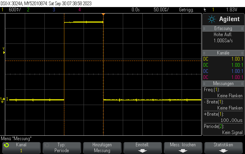
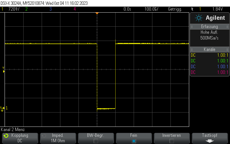
This is how the pulse looks like:

Full example:

#include <Arduino.h>
#include <esp_log.h>
#include <driver/rmt.h>

// Output pulse train on D14
constexpr gpio_num_t rmtPin = GPIO_NUM_14;
constexpr rmt_channel_t RMT_TX_CHANNEL = RMT_CHANNEL_0;

static const rmt_item32_t pulseRMT[] = {
    {{{
      /*pulse duration=*/100, /*pulse level*/0,
      // After pulse, output 1
      0, 1
    }}},
};

void setup() {
  Serial.begin(115200);

  rmt_config_t config = RMT_DEFAULT_CONFIG_TX(rmtPin, RMT_TX_CHANNEL);
  config.clk_div = 80; // input clock 80 MHz => output clk 1 MHz
  config.tx_config.idle_level = RMT_IDLE_LEVEL_HIGH;
  config.tx_config.idle_output_en = true;

  ESP_ERROR_CHECK(rmt_config(&config));
  ESP_ERROR_CHECK(rmt_driver_install(config.channel, 0, 0));

}

void loop() {
  ESP_ERROR_CHECK(rmt_write_items(RMT_TX_CHANNEL, pulseRMT, sizeof(pulseRMT) / sizeof(rmt_item32_t), true));
  delay(10);
}


[env:esp32dev]
platform = espressif32
board = esp32dev
framework = arduino
monitor_speed = 115200


Posted by Uli Köhler in Arduino, C/C++, ESP8266/ESP32, PlatformIO

ESP32 RMT pulse generation minimal example using Arduino & PlatformIO

The following example will generate 100us pulses every 10ms. The pulses are generated using the RMT peripheral.

#include <Arduino.h>
#include <esp_log.h>
#include <driver/rmt.h>

// Output pulse train on D14
constexpr gpio_num_t rmtPin = GPIO_NUM_14;
constexpr rmt_channel_t RMT_TX_CHANNEL = RMT_CHANNEL_0;


static const rmt_item32_t pulseRMT[] = {
    {{{
      /*pulse duration=*/100, /*pulse level*/1,
      // After pulse, output 0
      0, 0
    }}},
};


void setup() {
  Serial.begin(115200);

  rmt_config_t config = RMT_DEFAULT_CONFIG_TX(rmtPin, RMT_TX_CHANNEL);
  config.clk_div = 80; // input clock 80 MHz => output clk 1 MHz

  ESP_ERROR_CHECK(rmt_config(&config));
  ESP_ERROR_CHECK(rmt_driver_install(config.channel, 0, 0));

}

void loop() {
  ESP_ERROR_CHECK(rmt_write_items(RMT_TX_CHANNEL, pulseRMT, sizeof(pulseRMT) / sizeof(rmt_item32_t), true));
  delay(10);
}


[env:esp32dev]
platform = espressif32
board = esp32dev
framework = arduino
monitor_speed = 115200


Posted by Uli Köhler in Arduino, C/C++, ESP8266/ESP32, PlatformIO

Working PlatformIO configuration for AVRISP MKII flashing Arduino Uno (ATMega328P)

The following configuration works for flashing the Arduino Uno with the AVRISP MKII:

[env:uno]
platform = atmelavr
board = uno
framework = arduino
upload_protocol= custom
upload_port = usb
upload_flags = 
   -C
   $PROJECT_PACKAGES_DIR/tool-avrdude/avrdude.conf 
   -p 
   $BOARD_MCU
   -P 
   $UPLOAD_PORT
   -c
   avrispmkII
 ;   -c stk500v2
upload_command = avrdude $UPLOAD_FLAGS -U flash:w:$SOURCE:i


Posted by Uli Köhler in Arduino, Embedded

Short pulse generation with Arduino Uno Part 4: NOP for loops

In our previous post, we used NOP instructions inserted in between direct GPIO register access instructions to create pulse widths variable with obtainable resolutions of 62.5ns.

One could now use a for loop to create multiple NOP instructions:

for (int i = 0; i < 3; i++)
{
    _NOP();
}

As a matter of fact, this performs exactly as using three NOPs manually (312.5ns pulse width) because it is inlined by the compiler, i.e. the compiler just generates three separate NOPs since the number of NOPs is known at compile time.

Were we instead to use a variable numNOPs and use volatile so the compiler is instructed to not assume it is constant:

volatile int numNOPs = 3;
for (int i = 0; i < numNOPs; i++)
{
  _NOP();
}

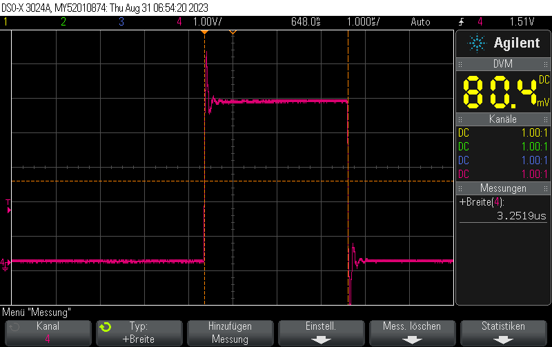
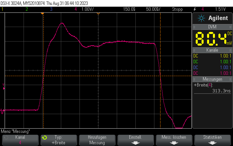
we’ll end up with a pulse width of not 312.5ns but 3250ns:

I measured the pulse width for different numNOPs settings:

  • numNOPs = 11.50us pulse width
  • numNOPs = 2: 2.25us pulse width
  • numNOPs = 33.00us pulse width
  • numNOPs = 4: 3.75us pulse width
  • numNOPs = 5: 4.5us pulse width
  • numNOPs = 6: 5.25us pulse width
  • numNOPs = 7: 6.00us pulse width
  • numNOPs = 86.75us pulse width
  • numNOPs = 9: 7.5us pulse width
  • numNOPs = 10: 8.25us pulse width

From this table it is obvious that the formula for the pulse width is

(\text{numNOPs} + 1) \cdot 0.75us

Why is it so much slower than manually pasting NOPs into it? Because the for loop introduces many additional instructions including memory load, compare and (conditional) jump into the machine instructions for your compiled program. This is why instead of 1instruction of length 62.5ns it actually takes 12 instructions of length 750ns to complete one iteration of the loop.

Full example

#include <Arduino.h>
#include <avr/io.h>

#define PORT11 PORTB
#define PIN11 3
#define PIN11_MASK (1 << PIN11)

void setup() {
    pinMode(11, OUTPUT);
}

volatile int numNOPs  = 1;

void loop() {
    cli();
    PORT11 |= PIN11_MASK;
    for (int i = 0; i < numNOPs; i++) {
        _NOP();
    }
    PORT11 &= ~PIN11_MASK;
    sei();

    delay(10);
}


Posted by Uli Köhler in Arduino, Electronics

Short pulse generation with Arduino Uno Part 3: Varying pulse width using “nop” instruction

In our previous post Short pulse generation with Arduino Uno Part 2: GPIO register access pulse width we detailed how to generate extremely short 125ns pulses using direct GPIO port register writes.

Given the code from our previous post, the pulse length can be varied with fairly high resolution using a NOPinstruction.

NOP instruction is a machine instruction for the microcontroller which does nothing (but doing nothing via NOP takes exactly one CPU cycle, which in effect leads to a very small delay). The delay is equivalent to one clock cycle – at 16 MHz master clock frequency such as for the Arduino Uno, this equates to 1/16MHz = 62.5ns.

We can integrate NOP into our code from the previous post by using the _NOP() macro which is available in #include <avr/cpufunc.h>

#define PORT11 PORTB
#define PIN11 3
#define PIN11_MASK (1 << PIN11)


void loop() {
    cli(); // Disable interrupts
    PORT11 |= PIN11_MASK; // Turn pin 11 on
    _NOP();
    PORT11 &= ~PIN11_MASK; // Turn pin 11 off
    sei(); // Enable interrupts again

    delay(10); // Wait 10ms
}

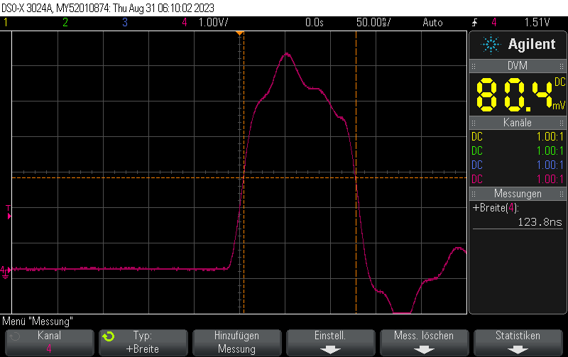
The original code without NOPs generated pulsed 125ns in width.

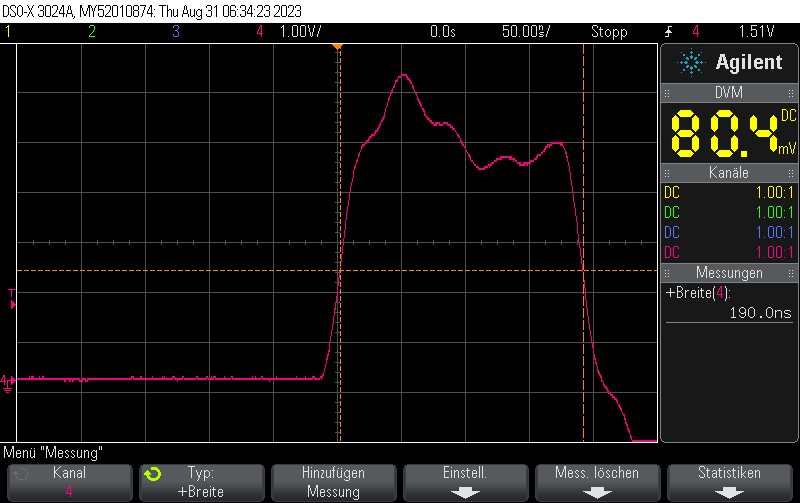
With one NOP instruction, it generates pulses 125ns + 62.5ns = 187.5ns in width:

Similarly, if we use two NOPs:

cli(); // Disable interrupts
PORT11 |= PIN11_MASK; // Turn pin 11 on
_NOP();
_NOP();
PORT11 &= ~PIN11_MASK; // Turn pin 11 off
sei(); // Enable interrupts again

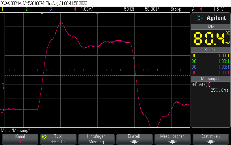
we will obtain pulses  125ns + 2*62.5ns = 250ns in width:

With three NOPs we’ll se pulses 125ns + 3*62.5ns = 312.5ns in width

Full example

#include <Arduino.h>
#include <avr/io.h>

#define PORT11 PORTB
#define PIN11 3
#define PIN11_MASK (1 << PIN11)

void setup() {
    pinMode(11, OUTPUT);
}

void loop() {
    cli();
    PORT11 |= PIN11_MASK;
    _NOP();
    _NOP();
    _NOP();
    PORT11 &= ~PIN11_MASK;
    sei();

    delay(10);
}


Posted by Uli Köhler in Arduino, Electronics

Short pulse generation with Arduino Uno Part 2: GPIO register access pulse width

When you use the following code to generate digital pulses with the Arduino Uno (cli() and sei() and to disable and enalbe interrupts in order to ensure consistent pulse width), you can generate the shortest possible pulses, limited by the Atmega328p’s 16MHz clock frequency:

#define PORT11 PORTB
#define PIN11 3
#define PIN11_MASK (1 << PIN11)


void loop() {
    cli(); // Disable interrupts
    PORT11 |= PIN11_MASK; // Turn pin 11 on
    PORT11 &= ~PIN11_MASK; // Turn pin 11 off
    sei(); // Enable interrupts again

    delay(10); // Wait 10ms
}

Based on the 16 MHz clock frequency of the ATMega328p, this generates pulses exactly almost exactly 125ns in lengh. This is equivalent to two clock cycles of the 16 MHz master clock.

Full example

#include <Arduino.h>
#include <avr/io.h>

#define PORT11 PORTB
#define PIN11 3
#define PIN11_MASK (1 << PIN11)

void setup() {
    pinMode(11, OUTPUT);
}

void loop() {
    cli();
    PORT11 |= PIN11_MASK;
    PORT11 &= ~PIN11_MASK;
    sei();

    delay(10);
}


Posted by Uli Köhler in Arduino, Electronics

Short pulse generation with Arduino Uno Part 1: digitalWrite() pulse width

When you use the following code to generate digital pulses with the Arduino Uno (cli() and sei() and to disable and enalbe interrupts in order to ensure consistent pulse width):

cli();
digitalWrite(outputPin, HIGH);
digitalWrite(outputPin, LOW);
sei();

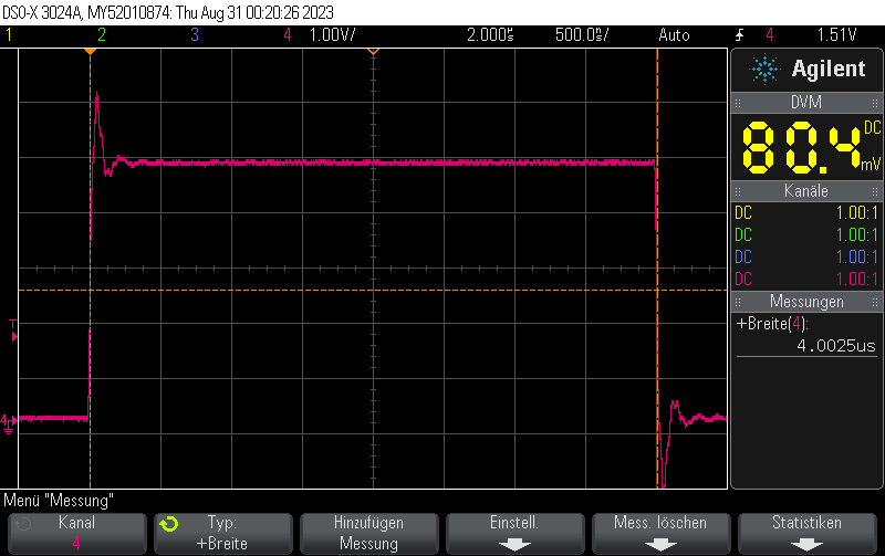
the time it takes to digitalWrite() dominates. Based on the 16 MHz clock frequency of the ATMega328p, this generates pulses exactly 4 microseconds in length:

Posted by Uli Köhler in Arduino, Electronics

ESP32 MAX31855 thermocouple LCD minimal example using PlatformIO

Important: In newer versions of PlatformIO, most ESP32 boards will crash with this example unless you create a custom lv_conf.h config file specifying to use internal memory instead of PSRAM. See How to fix ESP32 LVGL crash / reboot in lv_tlsf_create() / lv_mem_init() for instructions how to fix that.

In our previous example Adafruit ST7735R display minimal LVGL example for PlatformIO we showed how to use LVGL to display a simple text on a ST7735R-based SPI display.

In this post, we’ll extend this example by

See Minimal ESP32 PlatformIO TFT display example using Adafruit ST7735 for the recommended hardware configuration for the display. The code supports two MAX31855s but only one is used for this example. The pinout for the MAX31855 is:

constexpr int8_t Pin_MAX31855_CLK = 21;
constexpr int8_t Pin_MAX31855_MISO = 5;
constexpr int8_t Pin_MAX31855_A_CS = 18;

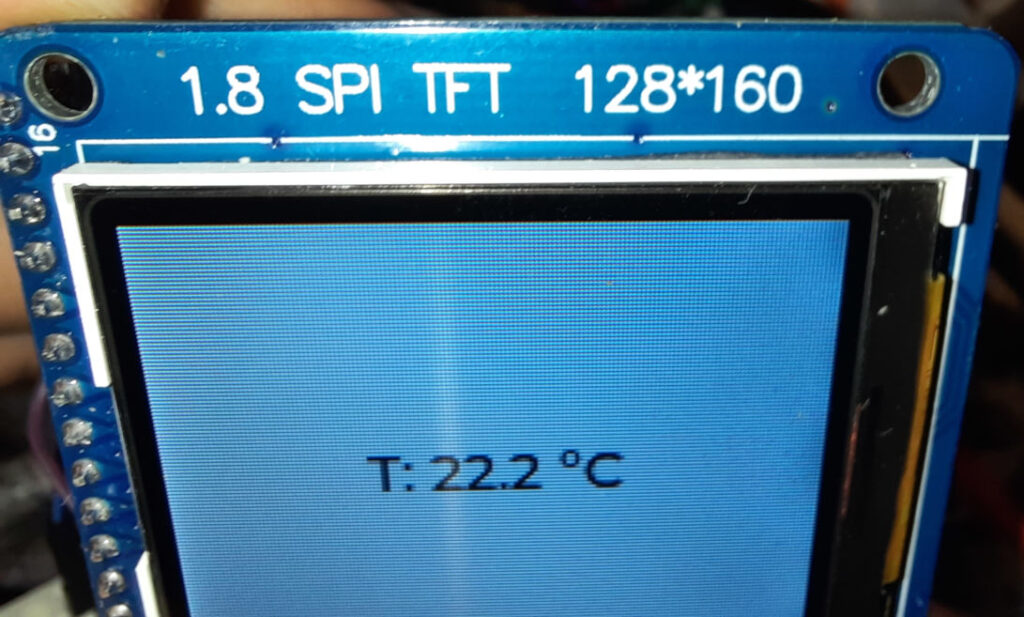
Using an ESP32 with a 128x160px ST7735R display, this code achieves a ~5Hz update rate. Note that this example can easily be modified to work with other LCD controllers or displays.

#include <Arduino.h>
#include <Adafruit_GFX.h>
#include <Adafruit_ST7735.h>
#include <Adafruit_LvGL_Glue.h>
#include <Adafruit_MAX31855.h>
#include <string>
#include <sstream>

constexpr int8_t Pin_LCD_CS = 27;
constexpr int8_t Pin_LCD_DC = 23;
constexpr int8_t Pin_LCD_RST = 22;
constexpr int8_t Pin_LCD_SCLK = 14;
constexpr int8_t Pin_LCD_MISO = 12;
constexpr int8_t Pin_LCD_MOSI = 13;

constexpr int8_t Pin_MAX31855_CLK = 21;
constexpr int8_t Pin_MAX31855_MISO = 5;
// Two different Chip selects for two different MAX31855
constexpr int8_t Pin_MAX31855_A_CS = 18;
constexpr int8_t Pin_MAX31855_B_CS = 19;

SPIClass vspi(VSPI);
Adafruit_MAX31855 thermocouple1(Pin_MAX31855_A_CS, &vspi);
Adafruit_MAX31855 thermocouple2(Pin_MAX31855_B_CS, &vspi);

Adafruit_ST7735 lcd(Pin_LCD_CS, Pin_LCD_DC, Pin_LCD_MOSI, Pin_LCD_SCLK,
                                 Pin_LCD_RST);
Adafruit_LvGL_Glue glue;


// Number of consecutive NaN reads before we assume the thermocouple is actually disconnected
uint32_t consecutiveNaNReads = 0;
constexpr uint32_t maxConsecutiveNaNReads = 10;
std::string labelText = "";
lv_obj_t *label;


void lvgl_setup(void) {
  // Create simple label centered on screen
  label = lv_label_create(lv_scr_act());
  lv_label_set_text(label, "Initializing..");
  lv_obj_align(label, LV_ALIGN_CENTER, 0, 0);
}


template<typename T>
std::string celsiusToString(const T a_value, const int decimals = 1)
{
    std::ostringstream out;
    out.precision(decimals);
    out << std::fixed << a_value << " °C";
    return std::move(out).str();
}

bool IsValidReading(double reading) {
  return !isnan(reading) && reading > -40.0 && reading < 1000.0;
}

void ReadTemperature() {
  double celsius = thermocouple1.readCelsius();
  if(!IsValidReading(celsius)) {
    consecutiveNaNReads++;
    if(consecutiveNaNReads >= maxConsecutiveNaNReads) {
      // Thermocouple is disconnected
      lv_label_set_text(label, "Error");
    }
  } else {
    consecutiveNaNReads = 0;
    labelText = "T: " + celsiusToString(celsius);
    lv_label_set_text(label, labelText.c_str());
  }
}

void setup() {
  Serial.begin(115200);
  // Start MAX31855 SPI
  vspi.begin(Pin_MAX31855_CLK, Pin_MAX31855_MISO, Pin_MAX31855_A_CS);

  lcd.initR(INITR_BLACKTAB);      // Init ST7735S chip, black tab
  lcd.setRotation(1);

  LvGLStatus status = glue.begin(&lcd);
  if(status != LVGL_OK) {
    Serial.printf("Glue error %d\r\n", (int)status);
    ESP.restart();
  }

  lvgl_setup(); // Call UI-building function above
}

void loop() {
  ReadTemperature();
  lv_task_handler(); // Call LittleVGL task handler periodically
  delay(5);
}
[env:esp32dev]
platform = espressif32
board = esp32dev
framework = arduino
monitor_speed = 115200
lib_deps =
    adafruit/Adafruit GFX Library@^1.11.5
    adafruit/Adafruit ST7735 and ST7789 Library@^1.10.0
    adafruit/Adafruit LittlevGL Glue Library@^2.1.4
    adafruit/SdFat - Adafruit Fork@^2.2.1
    lvgl/lvgl@^8.3.7
    adafruit/Adafruit MAX31855 library@^1.4.0


Posted by Uli Köhler in Arduino, LVGL, PlatformIO

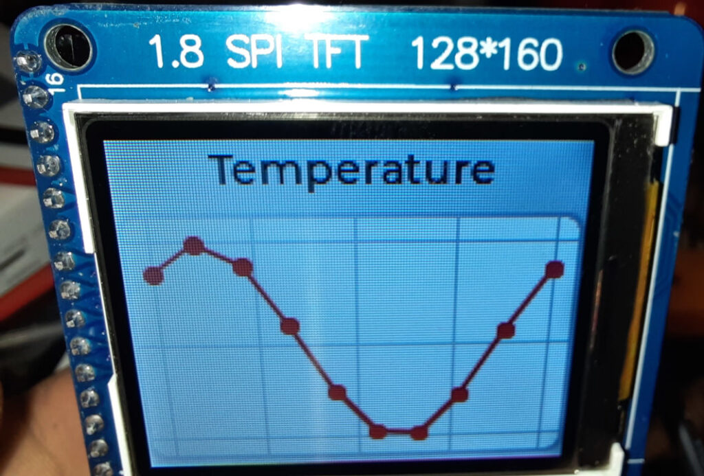
ST7735R LVGL live update chart example for PlatformIO

Important: In newer versions of PlatformIO, most ESP32 boards will crash with this example unless you create a custom lv_conf.h config file specifying to use internal memory instead of PSRAM. See How to fix ESP32 LVGL crash / reboot in lv_tlsf_create() / lv_mem_init() for instructions how to fix that.

In our previous example ST7735R minimal LVGL chart example for PlatformIO

See Minimal ESP32 PlatformIO TFT display example using Adafruit ST7735 for the recommended hardware configuration.

Using an ESP32 with a 128x160px ST7735R display, this code achieves a ~3Hz update rate. Note that this example can easily be modified to work with other LCD controllers or displays.

#include <Arduino.h>
#include <Adafruit_GFX.h>
#include <Adafruit_ST7735.h>
#include <Adafruit_LvGL_Glue.h>
#include <lvgl.h>
#include <string>

constexpr int Pin_LCD_CS = 27;
constexpr int Pin_LCD_DC = 23;
constexpr int Pin_LCD_RST = 22;
constexpr int Pin_LCD_SCLK = 14;
constexpr int Pin_LCD_MISO = 12;
constexpr int Pin_LCD_MOSI = 13;

Adafruit_ST7735 lcd(Pin_LCD_CS, Pin_LCD_DC, Pin_LCD_MOSI, Pin_LCD_SCLK,
                                 Pin_LCD_RST);
Adafruit_LvGL_Glue glue;

lv_obj_t* chart;
lv_chart_series_t * ser1;

void lvgl_chart_setup() {
    /*Create a chart*/
    chart = lv_chart_create(lv_scr_act());
    lv_obj_set_size(chart, 160, 100);
    lv_obj_align(chart, LV_ALIGN_BOTTOM_MID, 0, -3);
    lv_chart_set_type(chart, LV_CHART_TYPE_LINE);   /*Show lines and points too*/

    /*Add two data series*/
    ser1 = lv_chart_add_series(chart, lv_palette_main(LV_PALETTE_RED), LV_CHART_AXIS_PRIMARY_Y);

    /*Set the next points on 'ser1'*/
    lv_chart_set_next_value(chart, ser1, 10);
    lv_chart_set_next_value(chart, ser1, 10);
    lv_chart_set_next_value(chart, ser1, 10);
    lv_chart_set_next_value(chart, ser1, 10);
    lv_chart_set_next_value(chart, ser1, 10);
    lv_chart_set_next_value(chart, ser1, 10);
    lv_chart_set_next_value(chart, ser1, 10);
    lv_chart_set_next_value(chart, ser1, 30);
    lv_chart_set_next_value(chart, ser1, 70);
    lv_chart_set_next_value(chart, ser1, 90);

    lv_chart_refresh(chart);
}

void lvgl_setup(void) {
  // Create simple label centered on screen
  lv_obj_t *label = lv_label_create(lv_scr_act());
  lv_label_set_text(label, "Temperature");
  lv_obj_align(label, LV_ALIGN_TOP_MID, 0, 2);

  lvgl_chart_setup();
}

void setup() {
  Serial.begin(115200);
  lcd.initR(INITR_BLACKTAB);      // Init ST7735S chip, black tab
  lcd.setRotation(1);

  LvGLStatus status = glue.begin(&lcd);
  if(status != LVGL_OK) {
    Serial.printf("Glue error %d\r\n", (int)status);
    ESP.restart();
  }

  lvgl_setup(); // Call UI-building function above
}

void UpdateChart() {
  // Fill chart data with sine wave data
  float sineOffset = millis() / 1000.0;
  int16_t maxValue = 50;
  size_t count = lv_chart_get_point_count(chart);

  for (size_t i = 0; i < count; i++) {
    lv_chart_set_value_by_id(chart, ser1,  i, maxValue * (1 + sin((sineOffset + i) * 0.7)));
  }

  lv_chart_refresh(chart);
}

void loop() {
  // Update display
  UpdateChart();
  lv_task_handler();
  delay(5);
}
[env:esp32dev]
platform = espressif32 
board = esp32dev
framework = arduino
monitor_speed = 115200
lib_deps =
    adafruit/Adafruit GFX Library@^1.11.5
    adafruit/Adafruit ST7735 and ST7789 Library@^1.10.0
    adafruit/Adafruit LittlevGL Glue Library@^2.1.4
    adafruit/SdFat - Adafruit Fork@^2.2.1
    lvgl/lvgl@^8.3.7


Posted by Uli Köhler in Arduino, LVGL, PlatformIO

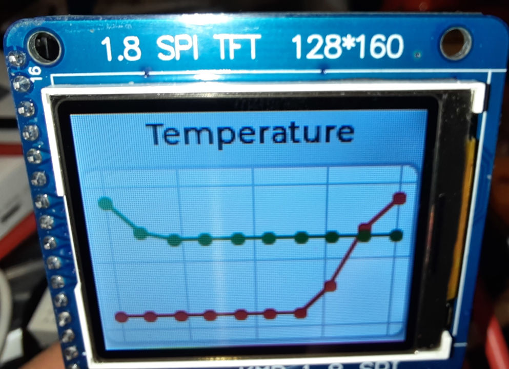
ST7735R minimal LVGL chart example for PlatformIO

Important: In newer versions of PlatformIO, most ESP32 boards will crash with this example unless you create a custom lv_conf.h config file specifying to use internal memory instead of PSRAM. See How to fix ESP32 LVGL crash / reboot in lv_tlsf_create() / lv_mem_init() for instructions how to fix that.

This example builds on our previous post Adafruit ST7735R display minimal LVGL example for PlatformIO

See Minimal ESP32 PlatformIO TFT display example using Adafruit ST7735 for the recommended hardware configuration.

Note that this example can easily be modified to work with other LCD controllers or displays.


#include <Arduino.h>
#include <Adafruit_GFX.h>
#include <Adafruit_ST7735.h>
#include <Adafruit_LvGL_Glue.h>
#include <lvgl.h>
#include <string>

constexpr int Pin_LCD_CS = 27;
constexpr int Pin_LCD_DC = 23;
constexpr int Pin_LCD_RST = 22;
constexpr int Pin_LCD_SCLK = 14;
constexpr int Pin_LCD_MISO = 12;
constexpr int Pin_LCD_MOSI = 13;

Adafruit_ST7735 lcd(Pin_LCD_CS, Pin_LCD_DC, Pin_LCD_MOSI, Pin_LCD_SCLK,
                                 Pin_LCD_RST);
Adafruit_LvGL_Glue glue;

void lvgl_chart_setup() {
    /*Create a chart*/
    lv_obj_t * chart;
    chart = lv_chart_create(lv_scr_act());
    lv_obj_set_size(chart, 160, 100);
    lv_obj_align(chart, LV_ALIGN_BOTTOM_MID, 0, -3);
    lv_chart_set_type(chart, LV_CHART_TYPE_LINE);   /*Show lines and points too*/

    /*Add two data series*/
    lv_chart_series_t * ser1 = lv_chart_add_series(chart, lv_palette_main(LV_PALETTE_RED), LV_CHART_AXIS_PRIMARY_Y);
    lv_chart_series_t * ser2 = lv_chart_add_series(chart, lv_palette_main(LV_PALETTE_GREEN), LV_CHART_AXIS_SECONDARY_Y);

    /*Set the next points on 'ser1'*/
    lv_chart_set_next_value(chart, ser1, 10);
    lv_chart_set_next_value(chart, ser1, 10);
    lv_chart_set_next_value(chart, ser1, 10);
    lv_chart_set_next_value(chart, ser1, 10);
    lv_chart_set_next_value(chart, ser1, 10);
    lv_chart_set_next_value(chart, ser1, 10);
    lv_chart_set_next_value(chart, ser1, 10);
    lv_chart_set_next_value(chart, ser1, 30);
    lv_chart_set_next_value(chart, ser1, 70);
    lv_chart_set_next_value(chart, ser1, 90);

    /*Directly set points on 'ser2'*/
    ser2->y_points[0] = 90;
    ser2->y_points[1] = 70;
    ser2->y_points[2] = 65;
    ser2->y_points[3] = 65;
    ser2->y_points[4] = 65;
    ser2->y_points[5] = 65;
    ser2->y_points[6] = 65;
    ser2->y_points[7] = 65;
    ser2->y_points[8] = 65;
    ser2->y_points[9] = 65;

    lv_chart_refresh(chart); /*Required after direct set*/
}

void lvgl_setup(void) {
  // Create simple label centered on screen
  lv_obj_t *label = lv_label_create(lv_scr_act());
  lv_label_set_text(label, "Temperature");
  lv_obj_align(label, LV_ALIGN_TOP_MID, 0, 2);

  lvgl_chart_setup();
}

void setup() {
  lcd.initR(INITR_BLACKTAB);      // Init ST7735S chip, black tab
  lcd.setRotation(1);

  LvGLStatus status = glue.begin(&lcd);
  if(status != LVGL_OK) {
    Serial.printf("Glue error %d\r\n", (int)status);
    ESP.restart();
  }

  lvgl_setup(); // Call UI-building function above
}

void loop() {
  lv_task_handler(); // Call LittleVGL task handler periodically
  delay(5);
}


[env:esp32dev]
platform = espressif32 
board = esp32dev
framework = arduino
lib_deps =
    adafruit/Adafruit GFX Library@^1.11.5
    adafruit/Adafruit ST7735 and ST7789 Library@^1.10.0
    adafruit/Adafruit LittlevGL Glue Library@^2.1.4
    adafruit/SdFat - Adafruit Fork@^2.2.1
    lvgl/lvgl@^8.3.7


Posted by Uli Köhler in Arduino, LVGL, PlatformIO

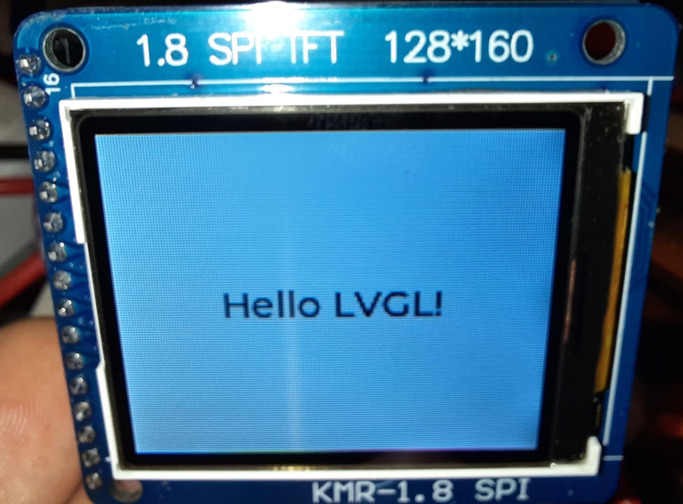
Adafruit ST7735R display minimal LVGL example for PlatformIO

Important: In newer versions of PlatformIO, most ESP32 boards will crash with this example unless you create a custom lv_conf.h config file specifying to use internal memory instead of PSRAM. See How to fix ESP32 LVGL crash / reboot in lv_tlsf_create() / lv_mem_init() for instructions how to fix that.

This example builds on the hardware & software setup outlined in Minimal ESP32 PlatformIO TFT display example using Adafruit ST7735 but uses the LVGL library to provide more advanced rendering possibilities.

See Minimal ESP32 PlatformIO TFT display example using Adafruit ST7735 for the hardware configuration.

Note that it’s just a minimal template to get started with LVGL, besides centered text rendering, no advanced LVGL techniques are being used.

#include <Arduino.h>
#include <Adafruit_GFX.h>
#include <Adafruit_ST7735.h>
#include <Adafruit_LvGL_Glue.h>
#include <string>

constexpr int Pin_LCD_CS = 27;
constexpr int Pin_LCD_DC = 23;
constexpr int Pin_LCD_RST = 22;
constexpr int Pin_LCD_SCLK = 14;
constexpr int Pin_LCD_MISO = 12;
constexpr int Pin_LCD_MOSI = 13;

Adafruit_ST7735 lcd(Pin_LCD_CS, Pin_LCD_DC, Pin_LCD_MOSI, Pin_LCD_SCLK,
                                 Pin_LCD_RST);
Adafruit_LvGL_Glue glue;

void lvgl_setup(void) {
  // Create simple label centered on screen
  lv_obj_t *label = lv_label_create(lv_scr_act());
  lv_label_set_text(label, "Hello LVGL!");
  lv_obj_align(label, LV_ALIGN_CENTER, 0, 0);
}

void setup() {
  lcd.initR(INITR_BLACKTAB);      // Init ST7735S chip, black tab
  lcd.setRotation(1);

  LvGLStatus status = glue.begin(&lcd);
  if(status != LVGL_OK) {
    Serial.printf("Glue error %d\r\n", (int)status);
    ESP.restart();
  }

  lvgl_setup(); // Call UI-building function above
}

void loop() {
  lv_task_handler(); // Call LittleVGL task handler periodically
  delay(5);
}
[env:esp32dev]
platform = espressif32 
board = esp32dev
framework = arduino
lib_deps =
    adafruit/Adafruit GFX Library@^1.11.5
    adafruit/Adafruit ST7735 and ST7789 Library@^1.10.0
    adafruit/Adafruit LittlevGL Glue Library@^2.1.4
    adafruit/SdFat - Adafruit Fork@^2.2.1
    lvgl/lvgl@^8.3.7


Posted by Uli Köhler in Arduino, LVGL, PlatformIO

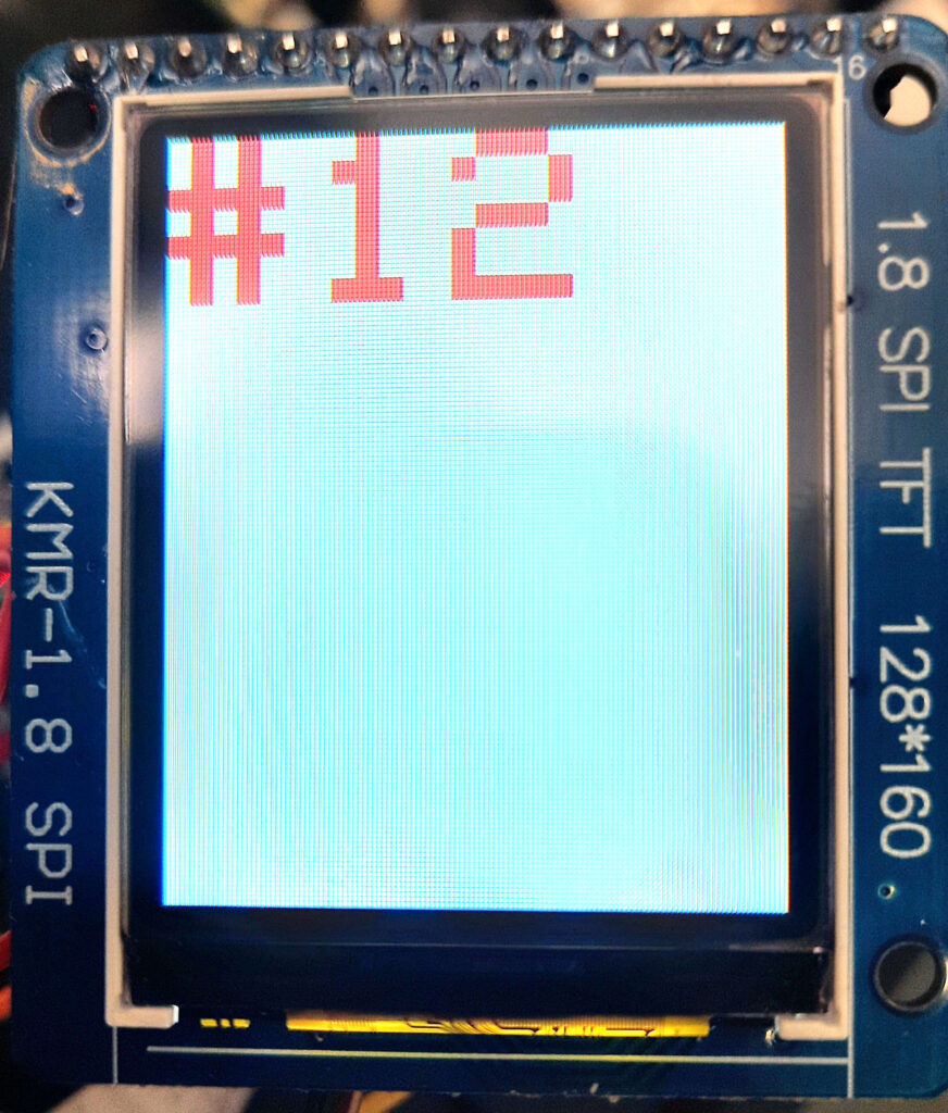
Adafruit ST7735R TFT display minimal text example for PlatformIO

This example builds on the hardware & software setup outlined in Minimal ESP32 PlatformIO TFT display example using Adafruit ST7735. See there for the PlatformIO example & hardware setup.

Our code displays a counter on the display that is updated every second. Only the rectangle from the last text draw is cleared, facilitating much faster screen updates than if clearing the entire screen. Also, this technique allows you to flexibly update only part of the screen instead of having to re-draw all other segments on update.

#include <Arduino.h>
#include <Adafruit_GFX.h>
#include <Adafruit_ST7735.h>
#include <string>

constexpr int Pin_LCD_CS = 27;
constexpr int Pin_LCD_DC = 23;
constexpr int Pin_LCD_RST = 22;
constexpr int Pin_LCD_SCLK = 14;
constexpr int Pin_LCD_MISO = 12;
constexpr int Pin_LCD_MOSI = 13;

Adafruit_ST7735 lcd(Pin_LCD_CS, Pin_LCD_DC, Pin_LCD_MOSI, Pin_LCD_SCLK,
                                 Pin_LCD_RST);

uint16_t backgroundColor = ST7735_WHITE;
uint16_t textColor = ST7735_RED;

void setup() {
  lcd.initR(INITR_BLACKTAB);      // Init ST7735S chip, black tab
  lcd.enableDisplay(true);        // Enable display
  // Fill screen with background color
  lcd.fillScreen(backgroundColor);
}

uint32_t counter = 0;

/**
 * The rectangle to clear the previous text
 * This is computed
 * 
 * @return int 
 */
struct Rect {
  int16_t x1;
  int16_t y1;
  uint16_t w;
  uint16_t h;
};
Rect lastTextRect;

void loop() {
  // The text we'll draw
  std::string text = "#" + std::to_string(counter);

  // Clear previous text
  if(!lastTextRect.w == 0 || !lastTextRect.h == 0) {
    lcd.fillRect(
      lastTextRect.x1,
      lastTextRect.y1,
      lastTextRect.w,
      lastTextRect.h,
      backgroundColor
    );
  }

  // Set position & parameters
  lcd.setCursor(0, 0);
  lcd.setTextColor(textColor);
  lcd.setTextWrap(true);
  lcd.setTextSize(5);

  // Compute bounding box of text text we'll draw
  // (so we can clear it later)
  lcd.getTextBounds(
    text.c_str(),
    lcd.getCursorX(),
    lcd.getCursorY(),
    &lastTextRect.x1,
    &lastTextRect.y1,
    &lastTextRect.w,
    &lastTextRect.h
  );
  
  lcd.print(text.c_str());
  delay(1000);
  counter++;
}


Posted by Uli Köhler in Arduino, PlatformIO

Minimal ESP32 PlatformIO TFT display example using Adafruit ST7735

This example code is for the KMR-1.8 SPI display (128x160px) and provides a minimal example using the Adafruit-ST7735 library that toggles the screen from black to white repeatedly. You can use this as a check if your hardware works correctly.

Hardware connection

Note that you can use any pin number on the ESP32 ; if you use other pins, ensure to change them in the code

  • Connect A0 or DC (whichever one exists on your board) to D23 on the ESP32 board.
  • Connect SCL (which is actually SPI SCK – the pin labeled SCK is just connected to the SD card!) to D14 on the ESP32 board.
  • Connect SDA (which is actually MOSI – the pin labeled MOSI is just connected to the SD card!) to D12 on the ESP32 board.
  • Connect CS to D27 on the ESP32 board.
  • ConnectRESET to D22 on the ESP32 board.
  • Connect LED- to GND on the ESP32 board.
  • Connect VCC to 3V3 on the ESP32 board.
  • Connect LED+ to 3V3 on the ESP32 board.
  • Connect Vcc to 3V3 on the ESP32 board.

Do not connect any pin to VIn or 5V. This can easily damage your display!

PlatformIO source code

#include <Arduino.h>
#include <Adafruit_GFX.h>
#include <Adafruit_ST7735.h>

constexpr int Pin_LCD_CS = 27;
constexpr int Pin_LCD_DC = 23;
constexpr int Pin_LCD_RST = 22;
constexpr int Pin_LCD_SCLK = 14;
constexpr int Pin_LCD_MISO = 12;
constexpr int Pin_LCD_MOSI = 13;

Adafruit_ST7735 lcd(Pin_LCD_CS, Pin_LCD_DC, Pin_LCD_MOSI, Pin_LCD_SCLK,
                                 Pin_LCD_RST);

void setup() {
  lcd.initR();      // Init ST7735S chip, black tab
  lcd.enableDisplay(true);        // Enable display
}

void loop() {
  delay(500);
  lcd.fillScreen(ST7735_BLACK);
  delay(500);
  lcd.fillScreen(ST7735_WHITE);
}
[env:esp32dev]
platform = espressif32
board = esp32dev
framework = arduino
lib_deps =
    adafruit/Adafruit GFX Library@^1.11.5
    adafruit/Adafruit ST7735 and ST7789 Library@^1.10.0


Posted by Uli Köhler in Arduino, PlatformIO

ESP-IDF HTTP webserver minimal ArduinoJson serialization example

static const httpd_uri_t valueHandler = {
    .uri       = "/api/value",
    .method    = HTTP_GET,
    .handler   = [](httpd_req_t *req) {
        httpd_resp_set_type(req, "application/json");
        // create json docuemnt
        DynamicJsonDocument json(1024);
        json["value"] = 1.0;
        // Serialize JSON to string
        std::string buf;
        serializeJson(json, buf);
        // Send response
        httpd_resp_send(req, buf.c_str(), buf.length());
        return ESP_OK;
    }
};

In order to add the ArduinoJson to PlatformIO, add the following lib_deps to platformio.ini:

lib_deps =
    [email protected]


Posted by Uli Köhler in Arduino, ESP8266/ESP32

How to read length-prefixed binary message from Serial using Arduino

The following function allows you to read a binary message, prefixed by a single length byte, from Serial:

#include <Arduino.h>

void setup() {
    Serial.begin(115200);
}

void HandleMessage(String msg) {
    // TODO: Your code to handle the message goes here.
    // See https://techoverflow.net/2022/11/15/how-to-print-string-as-sequence-of-hex-bytes-in-arduino/
    // for an example of how to print the message as a sequence of hex bytes.
}

void ReadMessageFromSerial() {
    // Wait until the length byte is available on Serial
    while (Serial.available() == 0);

    // Read the length of the message
    int length = Serial.read();

    // Read the rest of the message
    String message = "";
    for (int i = 0; i < length; i++) {
      while (Serial.available() == 0);
      message += char(Serial.read());
    }

    // Handle the message
    HandleMessage(message);
}

void loop() {
    ReadMessageFromSerial();
}


Posted by Uli Köhler in Allgemein, Arduino, Electronics, Embedded

How to use the ESP32 DAC sine/cosine waveform generator using Arduino / PlatformIO

The ESP32 and its derivatives such as the ESP32-S2 have a built-in sine/cosine waveform generator for the built-in 8-bit DAC.

Using it requires ESP-IDF v5.1+ (see the official example). Using it with Arduino is slightly harder, since the stable version of the arduino-esp32 framework at the time of writing this post is based on ESP-IDF v4.4 which does not provide the DAC cosine generator API.

Therefore, we have to explicitly specify the arduino-espressif32 version (git commit) in platformio.ini:

[env:esp32dev]
platform = espressif32
# Commit f9cddfde697b659b9e818ec514f1505d2bd4a8ae is branch esp-idf-v5.1-libs @2022-02-01
platform_packages = framework-arduinoespressif32 @ https://github.com/espressif/arduino-esp32.git#f9cddfde697b659b9e818ec514f1505d2bd4a8ae
board = esp32dev
framework = arduino

The example main source code is pretty simple:

#include <Arduino.h>
#include <driver/dac_cosine.h>

void setup() {
    dac_cosine_handle_t chan0_handle;
    dac_cosine_config_t cos0_cfg = {
        .chan_id = DAC_CHAN_1, // GPIO26
        .freq_hz = 1000,
        .clk_src = DAC_COSINE_CLK_SRC_DEFAULT,
        .atten = DAC_COSINE_ATTEN_DEFAULT,  
        .phase = DAC_COSINE_PHASE_0,  
        .offset = 0,
        //.flags.force_set_freq = false,
    };
    ESP_ERROR_CHECK(dac_cosine_new_channel(&cos0_cfg, &chan0_handle));
    ESP_ERROR_CHECK(dac_cosine_start(chan0_handle));
}

void loop() {
  // put your main code here, to run repeatedly:
  delay(1000);
}

If you want to see how the generated waveform looks on an oscilloscope, see How does the ESP32 DAC cosine generator waveform look on an Oscilloscope?

Posted by Uli Köhler in Arduino, ESP8266/ESP32, PlatformIO

STM32 HAL equivalent of Arduino millis()

The equivalent of Arduino’s millis() function when using the STM32 HAL is

HAL_GetTick()

The ticks occur once every millisecond, so this will also give you a millisecond timer that will overflow after some time equivalently to how millis() overflows.

Posted by Uli Köhler in Arduino, STM32

How to print WiFi MAC address to serial on ESP32 (Arduino)?

It’s as simple as

Serial.println(WiFi.macAddress());

Full example

#include <Arduino.h>

void setup() {
    Serial.begin(115200);
    Serial.println(WiFi.macAddress());
}

void loop() {
    // ...
}


Posted by Uli Köhler in Arduino, ESP8266/ESP32