Electronics

STC8 microcontroller P5.4 / RST pin functionality

STC8 microcontrollers have P5.4 which can (optionally) be used as device reset pin.

STC calls is a low-level reset pin, but in more standard terminology, it is an active-low reset pin

In order to select between using P5.4 as a ~RST pin or just a GPIO port (P5.4), set or unset bit P54RST (bit 4) in the RSTCFG register.

  • If bit P54RST is unset (binary 0), pin P5.4 can be used as a normal GPIO pin, the RST functionality is disabled
  • If bit P54RST is set (binary 1), pin P5.4 is used as a RST pin. It can’t be used as a normal GPIO pin in this mode


Source: STC8G Datasheet, section 6.3.3+

Posted by Uli Köhler in STC8

How to fix ESP32 ESP_LOGI(…) error: expected ‘)’ before ‘msg’

Problem:

You have code in your project such as

ESP_LOGI("MyTag", msg);

where msg is a const char*, but the project fails to compile with an error message such as

src/main.cpp:280:26: error: expected ')' before 'msg'
  280 |         ESP_LOGI("MyTag", msg);

Solution:

The format parameter can’t be any string but needs to be a string constant. Replace your code by

ESP_LOGI("MyTag", "%s", msg);


Posted by Uli Köhler in C/C++, ESP8266/ESP32

JLCPCB PCB assembly: List of known “Standard only” parts

For some parts, JLCPCB doesn’t support Economic PCBA but charges 25$ per assembly side for Standard PCBA.

You can find out which parts are Standard only by checking the JLCPCB component listStandard only parts are marked Standard only directly after the part number column while parts supporting economic PCBA are not marked at all.

Know parts include, according to my own research (this list is non-exhaustive and I don’t take any responsibility for correctness, beyond what’s legally required):


Posted by Uli Köhler in Electronics

Which distributors can JLCPCB source components from?

Please note: I can’t guarantee any of this, this is just according to my own research in April 2024

JLCPCB can order components from the following distributors:

  • DigiKey
  • Mouser
  • TTI
  • Chip1stop
  • Verical
  • Sager
  • Arrow
  • Element14 UK
  • Future
  • Powell
  • Avnet
  • Element
  • Onlinecomponents
  • Rutronik
  • CoreStaff
  • TME
Posted by Uli Köhler in Electronics

JLCPCB PCBA assembly price overview

This post summarizes JLCPCB fees. Please note that this is according to my own research in April 2024 and I can’t guarantee any of these prices or price structures in any way.

For reference, also see the official price list which lists most of these costs as well: https://jlcpcb.com/help/article/98-pcb-assembly-faqs

Economic vs standard PCBA

  • Economic PCBA: One-side only, 0$
  • Standard PCBA, 25$ for one-sided PCBA, 50$ for two-sided PCBA

Some parts such as ESP32 modules or WS2812-style LEDs force you to select standard PCBA.

See JLCPCB PCB assembly: List of known Standard only parts for more details.

Basic vs extended components

  • Basic components: 0$ per component type
  • Extended components: 2.74€/3$ per component type

SMT Assembly fees per solder joint

  • 0.0017$ per SMD pin

THT fees / Wave soldering fees

  • Manual assembly fee: 0.0173$ per THT pin. This is actually a wave soldering fee.
  • Fixed Hand soldering-fee3.22€/3.50$, this is actually a wave soldering fee with “assembly by hand”

Other fees

  • Special component fee: For USB-C connectors such as HC-TYPE-C-16P-01A, e.g. €0.1382 per component type (not per individual component)
  • Stencil: 1,38€/1.50$ fixed fee
  • Setup fee: 7,37€/8.00$ fixed fee
  • Panel: 0,00€, unclear how this is computed
  • Large size: 0.00€, unclear how this is computed
  • Components: How much your components cost, no additional markup.


Posted by Uli Köhler in Electronics

How to initialize your KiCAD 8 project on the command line

TL;DR:

Inside the directory where you want to create the project, run

wget -qO- https://raw.githubusercontent.com/ulikoehler/KiCAD-ProcessAutomation/master/InitializeKiCad8Project.sh | bash /dev/stdin MyProject

You should replace MyProject (at the end of the command) with your project name.

Note: This will initialize an empty KiCAD project without any libraries. This is equivalent to creating a new project in KiCAD itself (using the GUI).

Continue reading →

Posted by Uli Köhler in Electronics, KiCAD, Shell

How to fix pyspice OSError: cannot load library ‘libngspice.so’

Problem:

When trying to run a PySpice program, you see an error message such as

OSError: cannot load library 'libngspice.so': libngspice.so: cannot open shared object file: No such file or directory.  Additionally, ctypes.util.find_library() did not manage to locate a library called 'libngspice.so'

Solution:

Install libngspice, often called libngspice0.

On Ubuntu, install it using

sudo apt -y install libngspice0-dev

You need to install the -dev library since libngspice0 only contains libngspice.so.0 whereas the -dev library contains libngspice.so which is required by pyspice.

Posted by Uli Köhler in Python, SPICE

STM32 HAL PlatformIO LED blink example

In the autogenerated main.c, use the following while() loop:

/* Infinite loop */
/* USER CODE BEGIN WHILE */
while (1)
{
  /* USER CODE END WHILE */

  /* USER CODE BEGIN 3 */
  HAL_GPIO_WritePin(LD1_GPIO_Port, LD1_Pin, GPIO_PIN_SET);
  HAL_Delay(1000);
  HAL_GPIO_WritePin(LD1_GPIO_Port, LD1_Pin, GPIO_PIN_RESET);
  HAL_Delay(1000);
}
/* USER CODE END 3 */

On STM32H7 Nucleo boards, this will toggle the green LED.

Posted by Uli Köhler in C/C++, PlatformIO, STM32

What are the cheapest general purpose SMD diodes?

Typically some 1N4001…1N4007 in SOD-123 or SOD-123FL package is the cheapest available diode. It is available from many manufacturers and at all distributors.

The typical rating is:

  • 1A forward current
  • 1000V reverse voltage
  • Instantaneous forward voltage of <=1V @1A

On LCSC, a full reel (3000pcs) of SOD4007-MS by MSKSemi costs just 6,60€

Posted by Uli Köhler in Components

What cheap general purpose MOSFET to use?

The 2N7002 or 2N7002K MOSFET is one of the best MOSFETs to use if you just want to have a general purpose switching FET.

  • 60Vds
  • 300mA
  • 1.9Ohm RDSon

It or its variants is available from many manufacturers and at all distributors.

On LCSC, for example, one reel of 2N7002 from chinese manufacturer HL, only costs 15.90€, that is 0,0053€/pc

Posted by Uli Köhler in Components, Electronics

JST VH contact picture

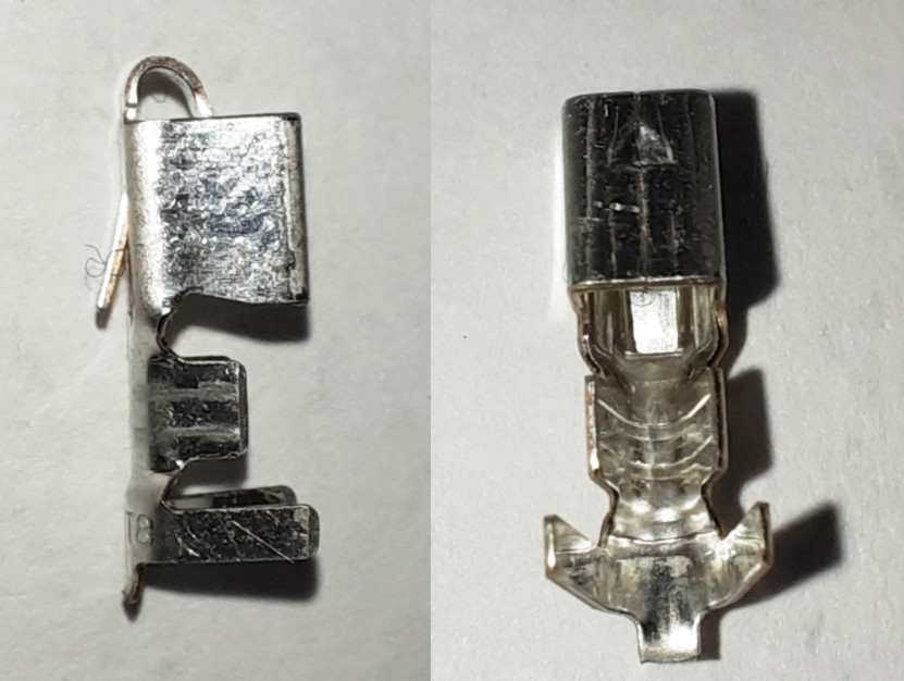
JST SVH-21T-P1.1 contact, for inventory management etc.

This picture is my own work and hereby released under CC0-1.0-Universal.

Posted by Uli Köhler in Electronics

How to fix PySpice WARNING – Unsupported Ngspice version 36

Problem:

When you try to run your PySpice script, you see an error log such as

PySpice.Spice.NgSpice.Shared.NgSpiceShared._send_char - WARNING - spinit was not found
PySpice.Spice.NgSpice.Shared.NgSpiceShared._send_char - ERROR - Note: can't find init file.
PySpice.Spice.NgSpice.Shared.NgSpiceShared._init_ngspice - WARNING - Unsupported Ngspice version 36

Solution:

Your PySpice is too new for the ngspice version installed on your system.

Typically, it’s easiest to install a slightly older PySpice version:

sudo pip3 install -U "pyspice<1.5"

(but you can also update your ngspice).

Posted by Uli Köhler in Electronics, Python

KiKit V-Cut panelization script template

#!/bin/sh
export DIRECTORY=panel
export PROJNAME=MyProject
mkdir -p $DIRECTORY
kikit panelize \
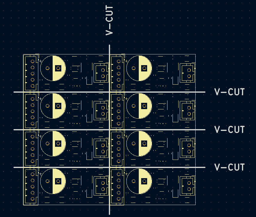
    --layout 'grid; rows: 4; cols: 2' \
    --tabs 'full' \
    --cuts 'vcuts ; layer: Edge.Cuts ; clearance: 0.4mm' \
    --post 'millradius: 2mm' \
    ${PROJNAME}.kicad_pcb ${DIRECTORY}/${PROJNAME}.kicad_pcb

Posted by Uli Köhler in KiCAD

KiKit breakaway tab panelization script template

#!/bin/sh
export DIRECTORY=panel
export PROJNAME=MyPCB
mkdir -p $DIRECTORY
kikit panelize \
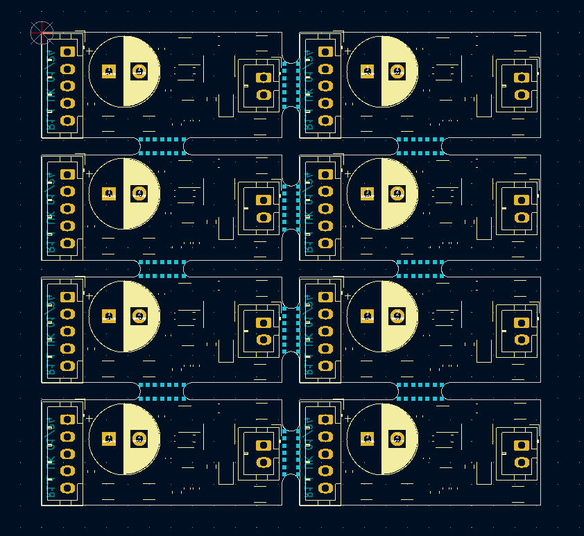
    --layout 'grid; rows: 4; cols: 2; space: 2mm' \
    --tabs 'fixed; width: 5mm' \
    --cuts 'mousebites; drill: 0.5mm; spacing: 0.8mm; offset: -0.2mm' \
    --post 'millradius: 1mm' \
    ${PROJNAME}.kicad_pcb ${DIRECTORY}/${PROJNAME}.kicad_pcb

Posted by Uli Köhler in KiCAD

How many MCPWM peripherals does the ESP32-S2 have?

The ESP32-S2 has no MCPWM (Motor control PWM) periperal.

However, the related ESP32-S3 features two MCPWM peripherals.

Source: Datasheet

Posted by Uli Köhler in ESP8266/ESP32

Measurement averaging code with fixed time windows for microcontrollers (C++)

This class performs averaging with a fixed time window (variable number of values).

From the platform, it only needs some method to get the current time. This code contains implementations for both ESP-IDF and Arduino

#pragma once
#include <optional>

// Find the correct driver
#ifdef ARDUINO
    #include <Arduino.h>
    #define TTAA_GETTIME_MILLIS millis()
#elif defined(IDF_VER) && !defined(ARDUINO)
    #include <esp_timer.h>
    #define TTAA_GETTIME_MILLIS esp_timer_get_time() / 1000
#else
    #error "Could not determine how to get the current time (Arduino or ESP-IDF)"
#endif

/**
 * @brief This class is designed to accumulate and average values over a specified time threshold.
 * 
 * The class is templated to allow accumulation of different numerical types, defaulting to float. It uses the Arduino `millis()`
 * function to track elapsed time, automatically calculating the average of accumulated values once the predefined time threshold is reached.
 * The `add()` method adds a new value to the accumulation, returning the average as a `std::optional<T>` when the threshold is reached,
 * and `std::nullopt` otherwise. The `lastAverage()` method allows retrieval of the last calculated average at any time.
 */
template<typename T = float>
class TimeThresholdAccumulatingAverager {
public:
    /**
     * Constructs a new TimeThresholdAccumulatingAverager object.
     * 
     * @param threshold The time threshold in milliseconds over which to accumulate and average values.
     */
    TimeThresholdAccumulatingAverager(unsigned long threshold) : _threshold(threshold), _startTime(TTAA_GETTIME_MILLIS), _sum(), _count() {}

    /**
     * Adds a value to the accumulator. If the time threshold has been reached, 
     * calculates and returns the average of the accumulated values since the last threshold reset.
     * Resets the accumulator for the next period if the threshold is reached.
     * 
     * The given value is not added to the current average if the threshold has been
     * exceeded. It is automatically added to the next period's average. 
     * 
     * @param value The value to add to the accumulator.
     * @return std::optional<T> The average of accumulated values if the threshold is reached, otherwise std::nullopt.
     */
    std::optional<T> add(T value) {
        unsigned long currentTime = TTAA_GETTIME_MILLIS;

        if (currentTime - _startTime >= _threshold) {
            // Time threshold exceeded. Calculcate average
            T average = _count > 0 ? _sum / static_cast<T>(_count) : 0;
            _lastCount = _count;
            // Reset sum & count to zero, but add the current value immediatey
            _sum = value;
            _count = 1;
            _startTime = currentTime;
            _lastAverage = average;
            return average;
        } else { // Time threshold not exceeded
            _sum += value;
            _count++;
            return std::nullopt;
        }

    }

    /**
     * Returns the average of the last completed accumulation period.
     * 
     * @return T The average value of the last completed period.
     */
    inline T lastAverage() const {
        return _lastAverage;
    }

    /**
     * Returns the count value of the last completed accumulation period.
     *
     * @return The last count value.
     */
    inline unsigned int lastCount() const {
        return _lastCount;
    }

private:
    unsigned long _threshold;
    unsigned long _startTime;
    T _sum;
    int _count = 0;
    T _lastAverage = 0;
    unsigned int _lastCount = 0;
};

Usage example:

#include <optional>
#include <iostream>

#include "TimeThresholdAccumulatingAverager.hpp"

int main() {
    TimeThresholdAccumulatingAverager<float> averager(1000); // 1 second threshold

    while (true) {
        float newValue = acquireValue(); // Pseudocode for acquiring a new value
        auto maybeAverage = averager.add(newValue);

        if (maybeAverage.has_value()) {
            std::cout << "Average over threshold period: " << average.value() << std::endl;
        }

        // Add a delay or wait for a real new value in a real application
        delay(10);
    }
}


Posted by Uli Köhler in Arduino, Embedded, ESP8266/ESP32, PlatformIO

How to provoke HardFault on STM32H7

((volatile int*)0xFFFFFFFF)[0] = 0;

This will perform an illegal memory access and hence trigger the hard faul. Due to voltatile, it won’t be optimized out by the compiler.

Posted by Uli Köhler in STM32

STM32H743 DAC instant switch off (no fall time)

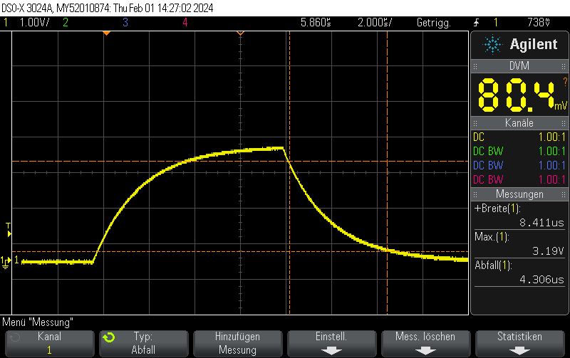
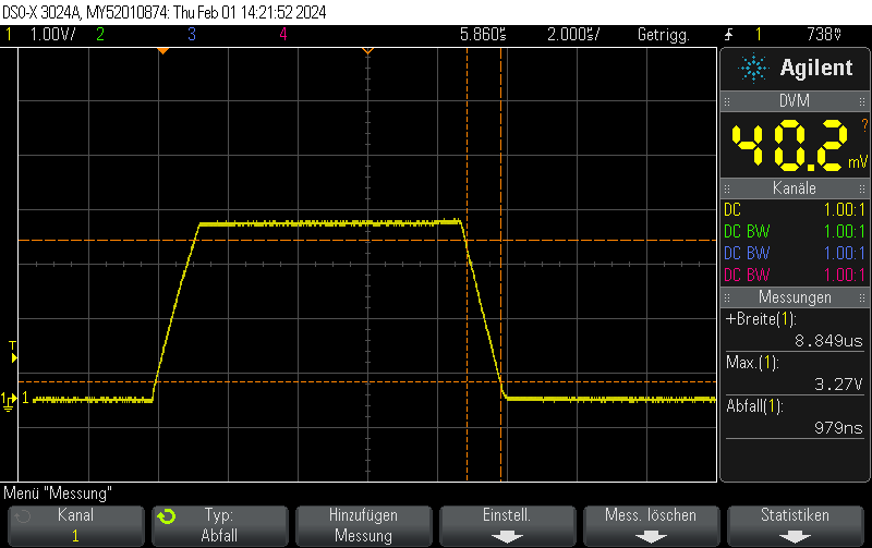
In our previous post STM32H743 DAC rise/fall time experiments we showed that the STM23H743 has relatively long turn-on / turn-off times of approximately 950 nanoseconds, limiting the generation of fast rectangular signals:
However, there’s a trick how to obtain fall times almost 3 orders of magnitude better for the special case of switching either to full-scale VDD or to GND.

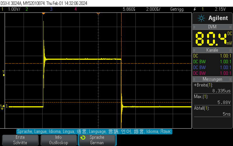
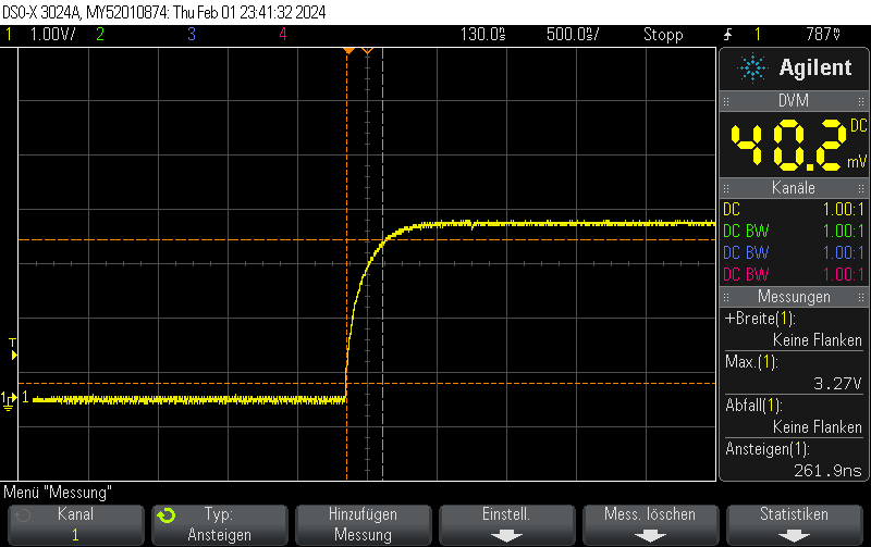
Instead of setting the DAC to the new value, you can just disable the DAC and let the GPIO take care of the rest. This allows for extremely fast fall times of approximately 5ns.

Note that switching the GPIO to digital mode while the DAC is on does not seem to have any effect.

Please note that I didn’t take any care to make the measurement setup immune to the high transients, leading to some oscillation. You should take your own measurements if you have specific requirements.
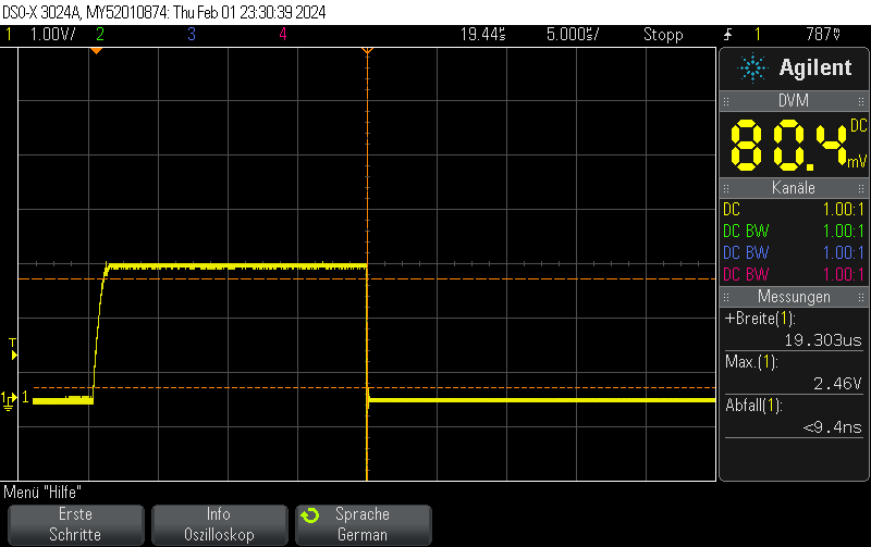
DAC fall time from 3/4 full scale value (3072)
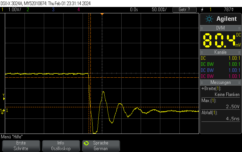
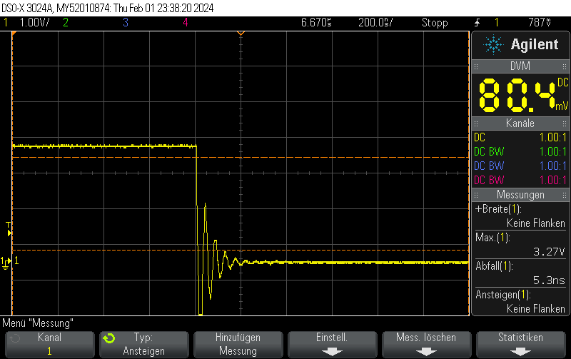
Note that switching on the DAC quickly is outside the scope of this post, but when toggling the DAC enable bit, you can still obtain 250ns rise times pretty easily.
Code example

void Init() {    
    DAC_ChannelConfTypeDef sConfig = {0};

    // Initialize DAC
    hdac.Instance = DAC1;
    if (HAL_DAC_Init(&hdac) != HAL_OK)
    {
        // Initialization Error
        __BKPT();
    }

    // Configure DAC channel
    sConfig.DAC_Trigger = DAC_TRIGGER_NONE;  // No trigger, free-running mode
    sConfig.DAC_OutputBuffer = DAC_OUTPUTBUFFER_ENABLE;

    if (HAL_DAC_ConfigChannel(&hdac, &sConfig, DAC_CHANNEL_1) != HAL_OK)
    {
        // Channel configuration Error
        __BKPT();
    }

    // Enable DAC Channel and start the conversion
    if (HAL_DAC_Start(&hdac, DAC_CHANNEL_1) != HAL_OK)
    {
        // Starting Error
        __BKPT();
    }

    // Set DAC to some value, which won't be changed for this example
    if (HAL_DAC_SetValue(&hdac, DAC_CHANNEL_1, DAC_ALIGN_12B_R, 3072) != HAL_OK)
    {
        // Setting DAC value Error
         __BKPT();
    }
}
void Pulse_On() {
    // Enable DAC
    hdac.Instance->CR |= DAC_CR_EN1;

    // Set GPIO to analog mode
    GPIO_InitTypeDef GPIO_InitStruct = {0};
    GPIO_InitStruct.Pin = GPIO_PIN_4;
    GPIO_InitStruct.Mode = GPIO_MODE_ANALOG;
    GPIO_InitStruct.Speed = GPIO_SPEED_FREQ_VERY_HIGH;
    GPIO_InitStruct.Pull = GPIO_NOPULL;
    HAL_GPIO_Init(GPIOA, &GPIO_InitStruct);
}

void Pulse_Off() {
    GPIO_InitTypeDef GPIO_InitStruct = {0};
    GPIO_InitStruct.Pin = GPIO_PIN_4;
    GPIO_InitStruct.Mode = GPIO_MODE_OUTPUT_PP;
    GPIO_InitStruct.Speed = GPIO_SPEED_FREQ_VERY_HIGH;
    GPIO_InitStruct.Pull = GPIO_NOPULL;
    HAL_GPIO_Init(GPIOA, &GPIO_InitStruct);
    HAL_GPIO_WritePin(GPIOA, GPIO_PIN_4, GPIO_PIN_RESET);

    // Clear EN1 bit of DAC_CR
    hdac.Instance->CR &= ~DAC_CR_EN1;
}


Posted by Uli Köhler in C/C++, STM32

STM32H743 DAC rise/fall time experiments

This oscilloscope trace was obtained by first setting the STM32H743ZI (Nucleo) DAC to 0x00, then setting it to maximum value (4096) without any intermediate steps.

The output buffer was enabled.

As can be seen on the trace, the rise/fall time is approximately 1us. No information about the clock speed etc is available for this example (Arduino on PlatformIO was used with standard settings). However, it does not appear that the rise/fall time is caused by the update rate. Setting the GPIO speed to maximum does not change the value.

This matches well with the datasheet-provided settling time of 1.7us(typ).

When disabling the output buffer, the result looks like this:

When, on the other hand, using the same pin as GPIO – using the exact same measurement setup (direct connection to BNC with 1M measurement impedance), the rise/fall time is almost zero.

Code example

// Function to initialize the DAC
void MX_DAC_Init(void)
{
    DAC_ChannelConfTypeDef sConfig = {0};

    // Initialize DAC
    hdac.Instance = DAC1;
    if (HAL_DAC_Init(&hdac) != HAL_OK)
    {
        // Initialization Error
        __BKPT();
    }

    // Configure DAC channel
    sConfig.DAC_Trigger = DAC_TRIGGER_NONE;  // No trigger, free-running mode
    sConfig.DAC_OutputBuffer = DAC_OUTPUTBUFFER_ENABLE;

    if (HAL_DAC_ConfigChannel(&hdac, &sConfig, DAC_CHANNEL_1) != HAL_OK)
    {
        // Channel configuration Error
        __BKPT();
    }

    // Enable DAC Channel and start the conversion
    if (HAL_DAC_Start(&hdac, DAC_CHANNEL_1) != HAL_OK)
    {
        // Starting Error
        __BKPT();
    }
}

The DAC value was set using

if (HAL_DAC_SetValue(&hdac, DAC_CHANNEL_1, DAC_ALIGN_12B_R, 4095) != HAL_OK) {
    // Setting DAC value Error
    __BKPT();
}


Posted by Uli Köhler in C/C++, STM32

How to find out if ESP-IDF framework is used using the preprocessor (PlatformIO)

You can use How to print all preprocessor flags in PlatformIO to print preprocessor flags. You can find all ESP-IDF related flags using

cat .pio/build/esp32dev/src/main.o | grep IDF

which is – with an empty main.c file just

#define IDF_VER "5.1.2"

Note that IDF_VER is also defined for Arduino since it is used internally by Arduino.

So you can use the following check which distinguistes between Arduino & ESP-iDF

#if !defined(ARDUINO) && defined(IDF_VER)
  // ESP-IDF code goes here
#else
  // Non-ESP-IDF code goes here
#else


Posted by Uli Köhler in ESP8266/ESP32