Electronics

Minimal component count voltage-controlled duty cycle PWM circuit

When given a stimulus PWM e.g. from a microcontroller or other oscillator, this simple circuit allows using a capacitor’s time constant to generate

The main trick here is to use the Schottky diode D1 to discharge the capacitor quickly when the stimulus PWM is low, and charging it slowly via R1.

The values used here are for MHz-frequency PWMs. Choose a R-C time constant suitable for your PWM frequency (R1 / C1). A good place to start is with the R-C time constant at 0.5 * period with period = 1/frequency. In general, you want the capacitor to be almost fully charged when the positive duty cycle period is over. You can compute the time constant using Wolfram Alpha.

If you are using larger capacitors than ~10nF, you should add a resistor in series with D1 to avoid killing the MCU output stage by dumping all the capacitor’s energy into it. Compute the resistor so that the maximum allowable input current equals the capacitor charge voltage (= typically the MCU supply voltage) minus the minimum diode forward voltage, across the resistor. This is a conservative choice, but you should start from there.

Keep in mind that the charge voltage is not linear, therefore the resulting voltage-controlled duty cycle is not linear with input voltage.

In order to allow a high duty cycle PWM output, the stimulus PWM should have almost 100% duty cycle. There must be enough time in the off-duty-cycle to properly discharge the capacitor via the Schottky diode.

Consider adding hysteresis to the comparator to avoid output oscillation.

The choice of diode doesn’t matter too much. Schottky diodes should be preferred because they tend discharge the capacitor more completely within less time: A 1N4148 would only discharge the capacitor to Vf~=0.7V, whereas the rest of the charge would have to flow out via the resistor. With Schottky diodes, this forward voltage is just 0.3V, in effect allowing a higher maximum duty cycle.

A single R/C/D circuit can be used to power multiple comparators, allowing multiple channels of voltage controlled PWM.

Measurement results

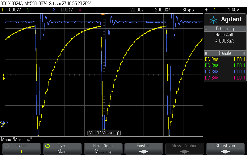
This is what it actually looks like. The voltage rise on the capacitor is fairly linear, it just appears to be oscillating due to inadequate effort being put into measuring this circuit. Keep in mind that this is not an ultra-precision circuit and in practice it’s not completely monotonous and certainly not linear in voltage.

The stimulus is given in blue. It’s a 4-bit 1.5MHz PWM with 15/16 duty cycle.

The capacitor voltage, which can be fed into the comparator, is shown in yellow.
 

Posted by Uli Köhler in Electronics

ESP32-S3 multiple frequency PWM output using the LEDC driver

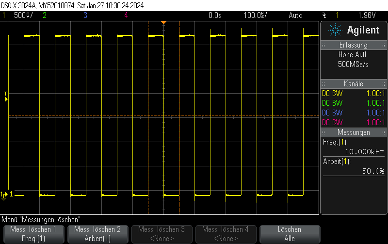
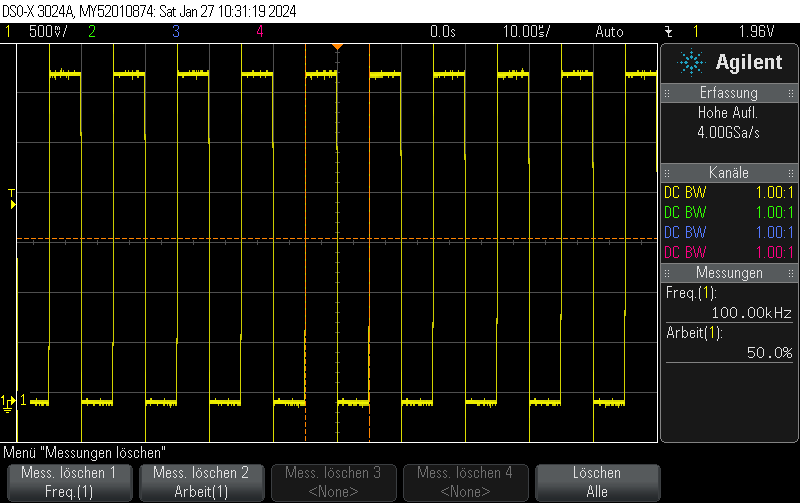
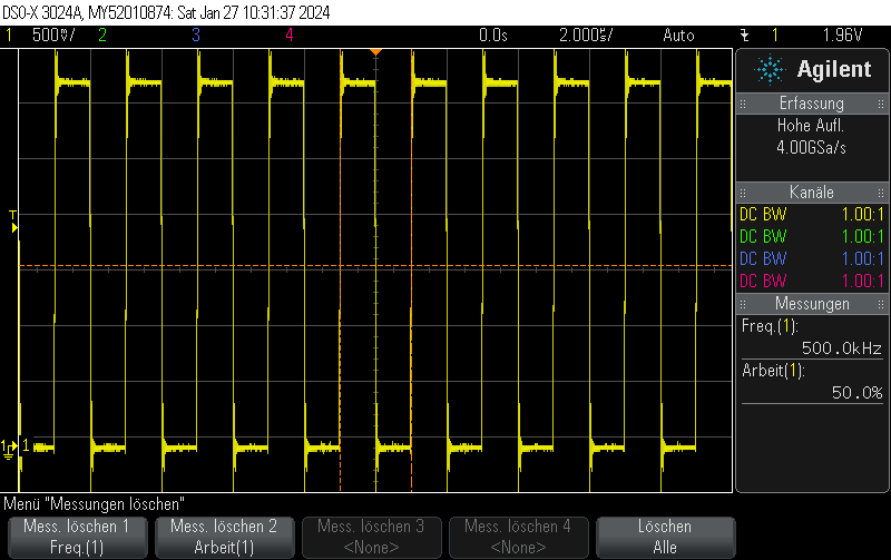
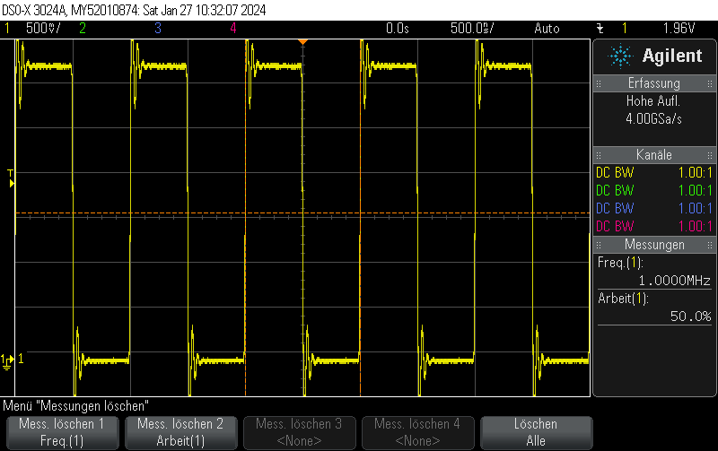
This Arduino/PlatformIO firmware outputs 50% duty cycle PWM at different frequencies on multiple pins using the LEDC PWM driver, utilizing all four timers:

  • 10 kHz on GPIO10
  • 100 kHz on GPIO11
  • 500 kHz on GPIO12
  • 1 MHz on GPIO13
#include <Arduino.h>
#include <driver/ledc.h>

void setup() {

  ledc_timer_config_t ledc_timer1 = {
      .speed_mode       = LEDC_LOW_SPEED_MODE,
      .duty_resolution  = LEDC_TIMER_1_BIT,
      .timer_num        = LEDC_TIMER_0,
      .freq_hz          = 10000,
      .clk_cfg          = LEDC_AUTO_CLK
  };
  ESP_ERROR_CHECK(ledc_timer_config(&ledc_timer1));

  ledc_timer_config_t ledc_timer2 = {
      .speed_mode       = LEDC_LOW_SPEED_MODE,
      .duty_resolution  = LEDC_TIMER_1_BIT,
      .timer_num        = LEDC_TIMER_1,
      .freq_hz          = 100000,
      .clk_cfg          = LEDC_AUTO_CLK
  };
  ESP_ERROR_CHECK(ledc_timer_config(&ledc_timer2));

  ledc_timer_config_t ledc_timer3 = {
      .speed_mode       = LEDC_LOW_SPEED_MODE,
      .duty_resolution  = LEDC_TIMER_1_BIT,
      .timer_num        = LEDC_TIMER_2,
      .freq_hz          = 500000,
      .clk_cfg          = LEDC_AUTO_CLK
  };
  ESP_ERROR_CHECK(ledc_timer_config(&ledc_timer3));

  ledc_timer_config_t ledc_timer4 = {
      .speed_mode       = LEDC_LOW_SPEED_MODE,
      .duty_resolution  = LEDC_TIMER_1_BIT,
      .timer_num        = LEDC_TIMER_3,
      .freq_hz          = 1000000,
      .clk_cfg          = LEDC_AUTO_CLK
  };
  ESP_ERROR_CHECK(ledc_timer_config(&ledc_timer4));


  /**
   * @brief Configure LEDC output channels
   */

  ledc_channel_config_t ledc1 = {
      .gpio_num       = GPIO_NUM_10,
      .speed_mode     = LEDC_LOW_SPEED_MODE,
      .channel        = LEDC_CHANNEL_0,
      .intr_type      = LEDC_INTR_DISABLE,
      .timer_sel      = LEDC_TIMER_0,
      .duty           = 1, // Set duty to 50%
      .hpoint         = 0
  };
  ESP_ERROR_CHECK(ledc_channel_config(&ledc1));

  ledc_channel_config_t ledc2 = {
      .gpio_num       = GPIO_NUM_11,
      .speed_mode     = LEDC_LOW_SPEED_MODE,
      .channel        = LEDC_CHANNEL_1,
      .intr_type      = LEDC_INTR_DISABLE,
      .timer_sel      = LEDC_TIMER_1,
      .duty           = 1, // Set duty to 50%
      .hpoint         = 0
  };
  ESP_ERROR_CHECK(ledc_channel_config(&ledc2));

  ledc_channel_config_t ledc3 = {
      .gpio_num       = GPIO_NUM_12,
      .speed_mode     = LEDC_LOW_SPEED_MODE,
      .channel        = LEDC_CHANNEL_2,
      .intr_type      = LEDC_INTR_DISABLE,
      .timer_sel      = LEDC_TIMER_2,
      .duty           = 1, // Set duty to 50%
      .hpoint         = 0
  };
  ESP_ERROR_CHECK(ledc_channel_config(&ledc3));

  ledc_channel_config_t ledc4 = {
      .gpio_num       = GPIO_NUM_13,
      .speed_mode     = LEDC_LOW_SPEED_MODE,
      .channel        = LEDC_CHANNEL_3,
      .intr_type      = LEDC_INTR_DISABLE,
      .timer_sel      = LEDC_TIMER_3,
      .duty           = 1, // Set duty to 50%
      .hpoint         = 0
  };
  ESP_ERROR_CHECK(ledc_channel_config(&ledc4));

}

void loop() {
  // Nothing to do here
  delay(1000);
}

GPIO10

GPIO11

GPIO12

GPIO13

Posted by Uli Köhler in Arduino, ESP8266/ESP32, PlatformIO

ESP32(-S3) ADC1 ESP-IDF minimal oneshot example with curve calibration

#include <esp_adc/adc_oneshot.h>
#include <esp_adc/adc_cali.h>
#include <esp_adc/adc_cali_scheme.h>


adc_oneshot_unit_handle_t adc1_handle = nullptr;
adc_cali_handle_t adc_cali_channel_handle = nullptr;

void InitADC() {
    //-------------ADC1 Init---------------//
    adc_oneshot_unit_init_cfg_t init_config1 = {
        .unit_id = ADC_UNIT_1,
    };
    ESP_ERROR_CHECK(adc_oneshot_new_unit(&init_config1, &adc1_handle));

    //-------------ADC1 Config---------------//
    adc_oneshot_chan_cfg_t config = {
        .atten = ADC_ATTEN_DB_11,
        .bitwidth = ADC_BITWIDTH_DEFAULT, // default width is max supported width
    };
    ESP_ERROR_CHECK(adc_oneshot_config_channel(adc1_handle, ADC_CHANNEL_6, &config));

    // Initialize 
    adc_cali_curve_fitting_config_t cali_config = {
        .unit_id = ADC_UNIT_1,
        .chan = ADC_CHANNEL_6,
        .atten = ADC_ATTEN_DB_11,
        .bitwidth = ADC_BITWIDTH_DEFAULT,
    };
    ESP_ERROR_CHECK(adc_cali_create_scheme_curve_fitting(&cali_config, &adc_cali_channel_handle));


}

void ADCRead() {
    // Read raw value
    int raw = 0;
    ESP_ERROR_CHECK(adc_oneshot_read(adc1_handle, ADC_CHANNEL_6, &raw));

    // Apply calibration to value
    int voltage = 0;
    ESP_ERROR_CHECK(adc_cali_raw_to_voltage(adc_cali_channel_handle, raw, &voltage));

    printf("ADC Channel[%d] Cali Voltage: %d mV\n", ADC_CHANNEL_6, voltage);
}

Usage example:

InitADC();
while(true)
{
    ADCRead();
    // Wait for some delay before reading again
    vTaskDelay(50 / portTICK_PERIOD_MS);
}

This prints, for example:

ADC Channel[6] Cali Voltage: 163 mV


Posted by Uli Köhler in C/C++, ESP8266/ESP32

ESP32(-S3) LEDC complementary output with programmable dead time example

On the ESP32 platform, you can use the LEDC PWM driver to generate programmable dead time by setting the duty (i.e. length of pulse) and hpoint(time offset of pulse) appropriately.

#include <driver/ledc.h>
ledc_timer_config_t ledc_timer = {
    .speed_mode       = LEDC_LOW_SPEED_MODE,
    .duty_resolution  = LEDC_TIMER_8_BIT,
    .timer_num        = LEDC_TIMER_0,
    .freq_hz          = 100000,
    .clk_cfg          = LEDC_AUTO_CLK
};
ESP_ERROR_CHECK(ledc_timer_config(&ledc_timer));

uint32_t deadTime = 20; // Large value to show clearly on the oscilloscope

ledc_channel_config_t ledc_noninverted_channel = {
    .gpio_num       = GPIO_NUM_10,
    .speed_mode     = LEDC_LOW_SPEED_MODE,
    .channel        = LEDC_CHANNEL_0,
    .intr_type      = LEDC_INTR_DISABLE,
    .timer_sel      = LEDC_TIMER_0,
    .duty           = 127-deadTime/2, // Set duty to 50%
    .hpoint         = 0
};
ESP_ERROR_CHECK(ledc_channel_config(&ledc_noninverted_channel));

ledc_channel_config_t ledc_complementary_channel = {
    .gpio_num       = GPIO_NUM_11,
    .speed_mode     = LEDC_LOW_SPEED_MODE,
    .channel        = LEDC_CHANNEL_1,
    .intr_type      = LEDC_INTR_DISABLE,
    .timer_sel      = LEDC_TIMER_0,
    .duty           = 127-deadTime/2, // Set cycle to start just after 50%
    .hpoint         = 127,
};
ESP_ERROR_CHECK(ledc_channel_config(&ledc_complementary_channel));

Posted by Uli Köhler in ESP8266/ESP32

ESP32(-S3) LEDC inverted output example

#include <driver/ledc.h>
ledc_timer_config_t ledc_timer = {
    .speed_mode       = LEDC_LOW_SPEED_MODE,
    .duty_resolution  = LEDC_TIMER_8_BIT,
    .timer_num        = LEDC_TIMER_0,
    .freq_hz          = 100000,
    .clk_cfg          = LEDC_AUTO_CLK
};
ESP_ERROR_CHECK(ledc_timer_config(&amp;ledc_timer));

ledc_channel_config_t ledc_inverted_channel = {
    .gpio_num       = GPIO_NUM_11,
    .speed_mode     = LEDC_LOW_SPEED_MODE,
    .channel        = LEDC_CHANNEL_1,
    .intr_type      = LEDC_INTR_DISABLE,
    .timer_sel      = LEDC_TIMER_0,
    .duty           = 128, // Set cycle to start just after 50%
    .hpoint         = 0,
    .flags = {.output_invert = true}
};
ESP_ERROR_CHECK(ledc_channel_config(&amp;ledc_inverted_channel));


Posted by Uli Köhler in ESP8266/ESP32

ESP32(-S3) LEDC complementary PWM example

#include <driver/ledc.h>
ledc_timer_config_t ledc_timer = {
    .speed_mode       = LEDC_LOW_SPEED_MODE,
    .duty_resolution  = LEDC_TIMER_8_BIT,
    .timer_num        = LEDC_TIMER_0,
    .freq_hz          = 100000,
    .clk_cfg          = LEDC_AUTO_CLK
};
ESP_ERROR_CHECK(ledc_timer_config(&ledc_timer));

ledc_channel_config_t ledc_noninverted_channel = {
    .gpio_num       = GPIO_NUM_10,
    .speed_mode     = LEDC_LOW_SPEED_MODE,
    .channel        = LEDC_CHANNEL_0,
    .intr_type      = LEDC_INTR_DISABLE,
    .timer_sel      = LEDC_TIMER_0,
    .duty           = 127, // Set duty to 50%
    .hpoint         = 0
};
ESP_ERROR_CHECK(ledc_channel_config(&ledc_noninverted_channel));

ledc_channel_config_t ledc_inverted_channel = {
    .gpio_num       = GPIO_NUM_11,
    .speed_mode     = LEDC_LOW_SPEED_MODE,
    .channel        = LEDC_CHANNEL_1,
    .intr_type      = LEDC_INTR_DISABLE,
    .timer_sel      = LEDC_TIMER_0,
    .duty           = 128, // Set cycle to start just after 50%
    .hpoint         = 0,
    .flags = {.output_invert = true}
};
ESP_ERROR_CHECK(ledc_channel_config(&ledc_inverted_channel));

Posted by Uli Köhler in ESP8266/ESP32

ESP32 rmt_tx sync manager minimal example

See ESP32 rmt_tx simple pulse example (ESP-IDF) for an example without sync manager

#include <driver/rmt_tx.h>
rmt_channel_handle_t channel;
rmt_tx_channel_config_t tx_chan_config = {
    .gpio_num = GPIO_NUM_19,          // GPIO number
    .clk_src = RMT_CLK_SRC_DEFAULT,   // select source clock
    .resolution_hz = 1 * 1000 * 1000, // 1 MHz resolution
    .mem_block_symbols = 64,          // memory block size, 64 * 4 = 256 Bytes
    .trans_queue_depth = 1,           // set the number of transactions that can pend in the background
};
ESP_ERROR_CHECK(rmt_new_tx_channel(&tx_chan_config, &channel));
ESP_ERROR_CHECK(rmt_enable(channel));

rmt_symbol_word_t txdata[64];
txdata[0] = {
    .duration0 = 100,
    .level0 = 1,
    .duration1 = 0,
    .level1 = 0,
};

// install sync manager
rmt_channel_handle_t tx_channels[] = {channel};
rmt_sync_manager_handle_t synchro = NULL;
rmt_sync_manager_config_t synchro_config = {
    .tx_channel_array = tx_channels,
    .array_size = sizeof(tx_channels) / sizeof(rmt_channel_handle_t),
};
ESP_ERROR_CHECK(rmt_new_sync_manager(&synchro_config, &synchro));

// Create simple encoder
rmt_copy_encoder_config_t encoder_config;
rmt_encoder_handle_t encoder;
ESP_ERROR_CHECK(rmt_new_copy_encoder(&encoder_config, &encoder));

rmt_transmit_config_t tx_config = {
    .loop_count = 0, // no transfer loop
};

while(true)
{
    ESP_ERROR_CHECK(rmt_transmit(channel, encoder, pulseRMT, 1*sizeof(rmt_symbol_word_t), &tx_config));
    // Wait for one second
    vTaskDelay(10 / portTICK_PERIOD_MS);
}


Posted by Uli Köhler in Allgemein, ESP8266/ESP32

ESP32 rmt_tx simple pulse example (ESP-IDF)

In contrast to our previous example from  ESP32 RMT pulse generation minimal example using Arduino &#038; PlatformIO this example uses the new rmt_tx API.

#include <driver/rmt_tx.h>
rmt_channel_handle_t channel;
rmt_tx_channel_config_t tx_chan_config = {
    .gpio_num = GPIO_NUM_19,          // GPIO number
    .clk_src = RMT_CLK_SRC_DEFAULT,   // select source clock
    .resolution_hz = 1 * 1000 * 1000, // 1 MHz resolution
    .mem_block_symbols = 64,          // memory block size, 64 * 4 = 256 Bytes
    .trans_queue_depth = 1,           // set the number of transactions that can pend in the background
};
ESP_ERROR_CHECK(rmt_new_tx_channel(&tx_chan_config, &channel));
ESP_ERROR_CHECK(rmt_enable(channel));

rmt_symbol_word_t txdata[64];
txdata[0] = {
    .duration0 = 100,
    .level0 = 1,
    .duration1 = 0,
    .level1 = 0,
};

// Create simple encoder
rmt_copy_encoder_config_t encoder_config;
rmt_encoder_handle_t encoder;
ESP_ERROR_CHECK(rmt_new_copy_encoder(&encoder_config, &encoder));

rmt_transmit_config_t tx_config = {
    .loop_count = 0, // no transfer loop
};

while(true)
{
    ESP_ERROR_CHECK(rmt_transmit(channel, encoder, pulseRMT, 1*sizeof(rmt_symbol_word_t), &tx_config));
    // Wait for one second
    vTaskDelay(10 / portTICK_PERIOD_MS);
}

Result:

Posted by Uli Köhler in ESP8266/ESP32

How to fix ESP32 rmt: rmt_transmit(476): channel not in enable state

If you get the following error during a rmt_transmit() call:

rmt: rmt_transmit(476): channel not in enable state

call

ESP_ERROR_CHECK(rmt_enable(channel));

after calling rmt_new_tx_channel().

Full initialization example

rmt_channel_handle_t channel;
rmt_tx_channel_config_t tx_chan_config = {
    .gpio_num = GPIO_NUM_19,          // GPIO number
    .clk_src = RMT_CLK_SRC_DEFAULT,   // select source clock
    .resolution_hz = 1 * 1000 * 1000, // 1 MHz resolution
    .mem_block_symbols = 64,          // memory block size, 64 * 4 = 256 Bytes
    .trans_queue_depth = 1,           // set the number of transactions that can pend in the background
};
ESP_ERROR_CHECK(rmt_new_tx_channel(&tx_chan_config, &channel));
ESP_ERROR_CHECK(rmt_enable(channel));


Posted by Uli Köhler in ESP8266/ESP32

How to manually run KiCad KLC visual-diff

The kicad-library-utils have a nice visual diff tools which can be used to compare different versions of symbols.

Run it manually on a symbol library such as Regulator_Switching.kicad_sym using

python ~/dev/kicad-library-utils/html-diff/src/html_diff.py $(git rev-parse origin/master) Regulator_Switching.kicad_sym

This will compare the currently checked-out revision to the current origin/master revision (you might need to git fetch --all to update the current revision).

It will produce a directory Regulator_Switching.diff, containing one HTML files for each changed symbol.

Example:

Regulator_Switching.diff
└── TPS62130.html


Posted by Uli Köhler in KiCAD

What are the MPNs for JST HL crimp contacts?

  • The male contact is called SSM-21T-P1.4LCSC link, 0.0227€/pc @1000pcs
  • The female contact is called SSF-21T-P1.4LCSC link 0.0205€/pc @1000pcs

Prices are for reference only.

Posted by Uli Köhler in Components

JLCPCB assembly: 2D or 3D picture

On 2023-12-28, a JLCPCB support agent told me that:

  • SMT components are assembled according to the 2D picture
  • Through hole components are assembled according to the 3D rendering

Therefore, you can ignore it if your through hole part looks slightly misplaced in the 2D rendering. It will always be assembled according to the placement 3D rendering.

Note: While I checked this information with the JLCPCB customer support, I do not take any responsibility beyond what’s required by law, for the correctness of this information. In other words: If your PCBs get mis-assembled, don’t blaim me. If in doubt, check with JLCPCB customer support. It’s not like they make it hard for you.

Posted by Uli Köhler in Electronics

How to set a fixed exposure time using libcamera-still on the Raspberry Pi

Use the --shutter argument. If no unit is given, the number represents microseconds of fixed exposure time

Example: --shutter 10000 means: Fixed 10 milliseconds (10000 microseconds) exposure.

Full example

libcamera-still -n 1 --width 4056 --height 3040 -o test.jpg --shutter 400


Posted by Uli Köhler in Raspberry Pi

How to enable Custom AWB white balance using libcamera-still on the Raspberry Pi

libcamera-still -n 1 --width 4056 --height 3040 -o test.jpg --awb custom --awbgains 0.9,2.0

In --awbgains 0.9,2.0 , 0.9 is the gain for the red channel and 2.0 is the gain for the blue channel.

In other words, if your image is:

  • too red -> decrease the first number
  • too blue -> decrease the second number
  • too yellow -> increase the second number (blue)
  • too green -> increase both numbers
  • etc
Posted by Uli Köhler in Raspberry Pi

Robust Linux Python serial port filtering by name and manufacturer using udev

Important note: This code is deprecated as it has been superseded by the UliSerial library on GitHub. UIiSerial implements the serial port filtering in a platform-independent manner using pyserial built-in features.


Typically, when one intends to select a serial port in Python, you use a sequence such as

glob.glob('/dev/ttyACM*')[0]

or just go to straight hard-coding the port such as /dev/ttyACM0.

It should be quite obvious why this isn’t robust:

  • There might be multiple serial ports and the order is unknown
  • You code might need to work on different computers, which lead to different ports being assigned
  • When you re-plug a device, it might get assigned a differnent serial port number (e.g. /dev/ttyACM1)

The following code uses only the linux integrated tool udevadm to query information and built-in libraries. Currently it does not work on anything but Linux.

import glob
import subprocess
import re

def get_serial_ports():
    # Get a list of /dev/ttyACM* and /dev/ttyUSB* devices
    ports = glob.glob('/dev/ttyACM*') + glob.glob('/dev/ttyUSB*')
    return ports

def get_udev_info(port):
    # Run the udevadm command and get the output
    result = subprocess.run(['udevadm', 'info', '-q', 'all', '-r', '-n', port], capture_output=True, text=True)
    return result.stdout

def find_serial_ports(vendor=None, model=None, usb_vendor=None, usb_model=None, usb_model_id=None, vendor_id=None):
    # Mapping of human-readable names to udevadm keys
    attribute_mapping = {
        "vendor": "ID_VENDOR_FROM_DATABASE",
        "model": "ID_MODEL_FROM_DATABASE",
        "usb_vendor": "ID_USB_VENDOR",
        "usb_model": "ID_USB_MODEL_ENC",
        "usb_model_id": "ID_USB_MODEL_ID",
        "vendor_id": "ID_VENDOR_ID",
        "usb_path": "ID_PATH",
        "serial": "ID_SERIAL_SHORT"
    }

    # Filters based on provided arguments
    filters = {}
    for key, value in locals().items():
        if value and key in attribute_mapping:
            filters[attribute_mapping[key]] = value

    # Find and filter ports
    ports = get_serial_ports()
    filtered_ports = []

    for port in ports:
        udev_info = get_udev_info(port)
        match = True

        for key, value in filters.items():
            if not re.search(f"{key}={re.escape(value)}", udev_info):
                match = False
                break

        if match:
            filtered_ports.append(port)

    return filtered_ports

def get_serial_port_info(port):
    # Mapping of udevadm keys to human-readable names
    attribute_mapping = {
        "ID_VENDOR_FROM_DATABASE": "vendor",
        "ID_MODEL_FROM_DATABASE": "model",
        "ID_USB_VENDOR": "usb_vendor",
        "ID_USB_MODEL_ENC": "usb_model",
        "ID_USB_MODEL_ID": "usb_model_id",
        "ID_VENDOR_ID": "vendor_id",
        "ID_SERIAL_SHORT": "serial",
    }

    # Run the udevadm command and get the output
    udev_info = get_udev_info(port)
    port_info = {}

    for line in udev_info.splitlines():
        if line.startswith('E: '):
            key, value = line[3:].split('=', 1)
            if key in attribute_mapping:
                # Decode escape sequences like \x20 to a space.
                # NOTE: Since only \x20 is common, we currently only replace that one
                port_info[attribute_mapping[key]] = value.replace('\\x20', ' ')

    return port_info

def find_serial_port(**kwargs):
    """
    Find a single serial port matching the provided filters.
    """
    ports = find_serial_ports(**kwargs)
    if len(ports) > 1:
        raise ValueError("Multiple matching ports found for filters: " + str(kwargs))
    elif len(ports) == 0:
        raise ValueError("No matching ports found for filters: " + str(kwargs))
    else:
        return ports[0]


Example: Find a serial port

# Example usage: Find a serial port
matching_ports = find_serial_ports(vendor="OpenMoko, Inc.")
print(matching_ports) # Prints e.g. ['/dev/ttyACM0']

Example: Print information about a given port

This is typically used so you know what filters to add for find_serial_ports().

# Example usage: Print info about a serial port
serial_port_info = get_serial_port_info('/dev/ttyACM0')
print(serial_port_info)

This prints, for example:

{
    'serial': '01010A23535223934CF29A1EF5000007',
    'vendor_id': '1d50',
    'usb_model': 'Marlin USB Device',
    'usb_model_id': '6029',
    'usb_vendor':
    'marlinfw.org',
    'vendor': 'OpenMoko, Inc.',
    'model': 'Marlin 2.0 (Serial)'
}


Posted by Uli Köhler in Electronics, Linux, Python

ESP32 HTTP POST with JSON body using ArduinoJson

This example parses a HTTP POST request body using ArduinoJson. I recommend using my HumanESPHTTP library as simple server library based on the ESP-IDF HTTP server.

constexpr size_t JsonParseBufferSize = 2048;
typedef ArduinoJson::StaticJsonDocument JsonParseBuffer;

/**
 * This buffer is used to parse /api/configure events
*/
static JsonParseBuffer document;

static const httpd_uri_t configureHandler = {
    .uri       = "/api/configure",
    .method    = HTTP_POST,
    .handler   = [](httpd_req_t *req) {
        // Receive POST body data into a new buffer
        char* jsonBody = (char*)malloc(req->content_len + 1);
        jsonBody[req->content_len] = '\0'; // NUL terminate [just in case]
        if(jsonBody == nullptr) {
            return SendStatusError(req, "Failed to allocate memory for JSON body");
        }
        int err = httpd_req_recv(req, jsonBody, req->content_len);
        if(err != req->content_len) {
            free(jsonBody);
            return SendStatusError(req, "Failed to read request body");
        }
        // Parse the body as JSON
        deserializeJson(document, jsonBody, req->content_len);
        // TODO: Do something with [document]
        // Cleanup
        free(jsonBody);
        return SendStatusOK(req);
    }
};

which uses the following utility functions:

esp_err_t SendStatusError(httpd_req_t *request, const char* description) {
    httpd_resp_set_type(request, "application/json");
    httpd_resp_send_chunk(request, "{\"status\":\"error\", \"error\": \"", HTTPD_RESP_USE_STRLEN);
    // NOTE: We silently assume that description does not have any special characters
    httpd_resp_send_chunk(request, description, HTTPD_RESP_USE_STRLEN);
    httpd_resp_send_chunk(request, "\"}", HTTPD_RESP_USE_STRLEN);
    httpd_resp_send_chunk(request, nullptr, 0); // Finished
    return ESP_OK;
}

esp_err_t SendStatusOK(httpd_req_t *request) {
    httpd_resp_set_type(request, "application/json");
    httpd_resp_sendstr(request, "{\"status\":\"ok\"}");
    return ESP_OK;
}


Posted by Uli Köhler in C/C++, ESP8266/ESP32

How to fix ESP32 rmt: rmt_transmit(466): loop count is not supported

If you encounter

rmt: rmt_transmit(466): loop count is not supported

on the ESP32, this is because you have used a rmt_transmit_config_t with explicitly set loop_count.

rmt_transmit_config_t cfg = {
  .loop_count = 1,
  .flags = {
      .eot_level = 0,
   }
};
ESP_ERROR_CHECK(rmt_transmit(/* ... */, &cfg));

but your IC (e.g. ESP32-D0WD-V3)  does not support hardware loop mode.

Fixing this is easy: Just comment out the .loop_count line:

rmt_transmit_config_t cfg = {
  //.loop_count = 1, // DISABLED as chip does not support it
  .flags = {
      .eot_level = 0,
   }
};
ESP_ERROR_CHECK(rmt_transmit(/* ... */, &cfg));

Note that if you leave .loop_count at its default, it will always act as if .loop_count = 1.

Posted by Uli Köhler in C/C++, ESP8266/ESP32

ESP32-D0WD-V3 does not support RMT sync manager

I was trying to use a RMT sync manager on the ESP32-D0WD-V3 (Version 3.1). However, trying to use rmt_new_sync_manager() returns ESP_ERR_NOT_SUPPORTED with the following message:

␛[0;31mE (560) rmt: rmt_new_sync_manager(331): sync manager not supported␛[0m
ESP_ERROR_CHECK failed: esp_err_t 0x106 (ESP_ERR_NOT_SUPPORTED) at 0x400d2681

This leads me to believe that the ESP32-D0WD-V3 does not support any RMT sync managers. So far, I have not tried with other controllers.

Posted by Uli Köhler in ESP8266/ESP32