Electronics

Beware of the STM32 LSI: Its tolerance is up to ±47%

The STM32 LSI oscillator might seem like an attractive choice for RTC, IWDG Watchdog etc – without external components and

But one fact is often overlooked: Since it is internally a RC oscillator, it has an extremely high tolerance.

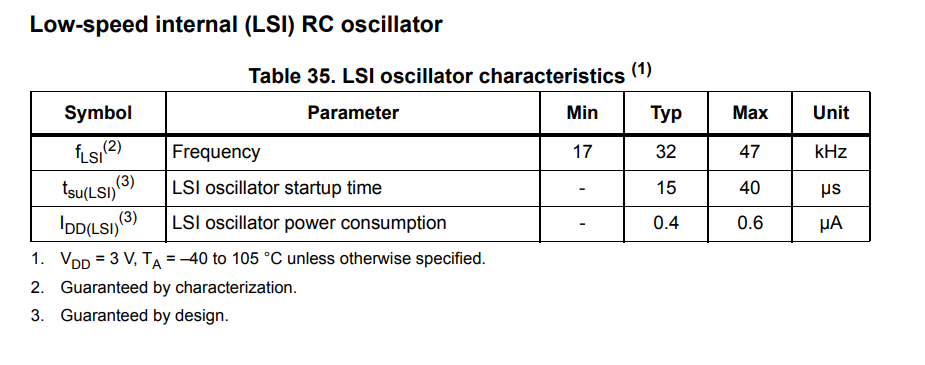
By looking at the STM32F407 datasheet, for example, we can see that its tolerance is ±47%

In other words, the LSI clock can run half as slow or 1.5 times as fast as expected.

±47% is equivalent to ±470 000 ppm whereas any normal crystal has a tolerance of ±20 ppm.

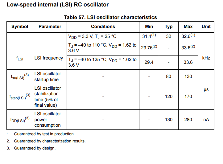
More recent STM32 families like the STM32H747XI have improved LSI accuracy:

This amounts to a tolerance of ±1.875 % which is equivalent to ±18 750 ppm – still orders of magnitude more than any crystal or even ceramic resonator.

Can you tune out the difference by RTC digital tuning?

The STM32 digital tuning only has a range of -487.1 ppm to +488.5 ppm – but even for the much more accurate STM32H747XI, you would need a tuning range of at least ±20 000 ppm in order to compensate for initial inaccuracies and temperature coefficient.

What can you do to get better accuracy?

Typically, I recommend to just use a crystal for the RTC – or use an external RTC altogether.

Regarding the IWDG, you have no choice but to use the LSI. Typically you can just select a longer reset interval to avoid unintended watchdog resets if your LSI is running much faster than the standard 32 kHz, or you can just reset the watchdog more often. If you reset your watchdog in an interrupt, you should consider using a higher priority interrupt – and do global interrupt disables less frequently and try to avoid having periods where interrupts are disabled globally for a long time continously.


Posted by Uli Köhler in Electronics, STM32

How to tune your crystal oscillator to get the best possible frequency accuracy

In our previous post How to compute crystal load capacitors using Python we investigated how to use UliEngineering to compute the appropriate load capacitor for your crystal oscillator.

Once you have manufactured your board, you should go one step further and tune your crystal oscillator.

Note that in this post we’re not talking about specialized compensated or heated crystals like TCXOs, DCXOs or OCXOs, but about your normal crystal which you use to clock your RTC, your microcontroller, your Ethernet PHY, your ADC, …

Also, this post is not made primarly for ppm hunters who desire to get below-±5ppm accuracy. While you certainly need to apply the techniques outlined here very carefully to get below your magic ppm number, they will likely not be sufficient.

Tuning the load capacitor

Note that for new PCBs, the stray PCB capacitance is just an educated guess – so your load capacitance will be slightly off.

First, you need to remember: Too low a load capacitance will result in higher frequency – too high a load capacitance will result in lower frequency.

I do not recommend to measure the PCB capacitance directly, because capacitances in the single picofarads are hard to measure accurately. Additionally, you can’t just measure them on a spare board without all the components (since the components, for example the case of the crystal, will affect the stray capacitance) but you also can’t just measure it on a fully populated board since the crystal itself will strongly influence your measurement.

Instead, just measure the  frequency of the crystal oscillator by measuring a reference clock output. The most appropriate instrument for that is a frequency counter with a sufficiently stable frequency source. Oscilloscopes typically don’t have the resolution required to measure a frequency down to the ppms. But if you have a microcontroller board with a sufficiently stable crystal.

Note that by attaching your probe to the crystal, you will load the crystal with additional capacitance from your probe, hence you won’t measure its actual frequency accurately. Do not probe your crystal directly but configure your RTC so that it generates a clock output on a separate pin and measure that.

Typically, your initially calculated load capacitor value will be within ±50% of the final value. Hence, you should buy approximately 5-20 standard values of capacitors within that range. Nowadays, buying 10 ceramic capacitors costs only around 0.15€ so just buying a buch of them is not really worth any consideration and you should just order them – or alternatively order a kit of capacitors. Note that standard capacitor values like 10pF or 6.2pF are often much cheaper than very specific values, so take care when selecting the values you buy.

For example, if you have a calculated load capacitor value of 7pF, you could order the following capacitors:

  • 3.5 pF
  • 4 pF
  • 5 pF
  • 6.2 pF
  • 7 pF
  • 8.2 pF
  • 10 pF

How accurately should you tune?

My recommendation on how accurately you should tune depends on whether exchanging components is the only type of tuning you can do or if your oscillator IC supports digital tuning. Since nowadays digital tuning is so easy and much more reproducible than changing components (due to tolerances etc)

If your RTC/controller does NOT support digital tuning: My recommendation is to tune no more than 2.5 times the specified accuracy of the crystal. So if your crystal has specified tolance of ±20ppm, in most applications you should tune to ±50ppm

If your controller supports digital tuning but not autotuning: My recommendation is to tune no more than 4 times the specified accuracy of the crystal. So if your crystal has specified tolance of ±20ppm, in most applications you should tune to ±80ppm

If your controller supports digital autotuning: My recommendation is to tune to Digital adjustment range / 1.5

In any case, remember that it’s a tradeoff between your time improving the product and slight inaccuracies that might

Digitally tuning the frequency

Many controllers and RTCs nowadays feature a circuit to digitally tune the frequency to up to sub-ppm levels using e.g. I2C access. Internally, this works by omitting or adding pulses to an internal clock every now and then, effectively decreasing or increasing the average frequency of the clock.

Note that you can’t just infinitely adjust using digital adjustment, a typical adjustment range will be ±100ppm to ±500ppm.

The most primitive variant is to just use the register where you enter how many PPMs up or down the frequency should be adjusted, do it once for your prototype and hope that your production run won’t be significantly different. In this case, you have little choice but to take your frequency counter, measure the frequency. Note that digital adjustment does not change the frequency of the crystal at all, but typically the reference output is digitally adjusted. Note however, that the adjustment might only happen every few minutes (read your RTC datasheet or reference manual for more info). The only way to reliably check if the change is effective is by letting the board run for a few days and observe how much it drifted compared to a reference clock.

A more advanced, albeit much harder to implement variant is to use a different (more accurate) reference clock source like an accurate oscillator or even OCXO, or a clock derived from USB (which some STM32 microcontrollers can do) or the power grid (which is not very accurate over short time spans but is very accurate over long time spans), implement a frequency counter in your MCU and automatically adjust the digital tuning parameters. The implementation of this highly depends on which MCU you are using and would exceed the scope of this post.
Posted by Uli Köhler in Electronics

How to compute crystal load capacitors using Python

The UliEngineering library provides a convenient way to compute which load capacitors are suitable for a given crystal oscillator circuit.

First, install UliEngineering using

sudo pip3 install UliEngineering

Now you need to find out the following parameters:

  • The load capacitance from the crystal’s datasheet. Typical values would be 7pF or 12.5pF or 20pF
  • The pin capacitance CPin from the datasheet of the IC your crystal is connected to (e.g. your Ethernet PHY or your RTC). Typical values would be between 0.5pF to 5pF
  • Estimate the stray capacitance CStray from the board (that is the capacitance of each crystal oscillator pin to the PCB ground). You typically just take an educated guess here, so here are some values to start at:
    •  Start at 3pF
    • If you have a 4+ layer board (as opposed to a two layer board), add 2pF (since the distance to the ground plane below is much smaller on 4 layer boards
    • If you have long traces >1cm (long traces to the crystal should be avoided at all costs!), add 4pF for each cm of trace beyond 1cm for 2-layer boards or add 6pF for each cm of trace beyond 1cm for 4+ layer boards

Now we’ll plug those values into UliEngineering and compute the load capacitance:

from UliEngineering.Electronics.Crystal import load_capacitors
from UliEngineering.EngineerIO import auto_print

auto_print(load_capacitors, cload="9 pF", cpin="1 pF", cstray="5 pF")

This will print 7.00 pF

If you just want to the the value and not an auto-formatted string, use load_capacitors() directly:

capacitor = load_capacitors(cload="9 pF", cpin="1 pF", cstray="5 pF")

In this example, we’ll get capacitor == 7e-12.

Note that 7pF means that you have to add a 7pF capacitor at each side of the crystal. I recommend to use only NP0/C0G capacitors here since X5R/X7R capacitors and other high-k-dielectric ceramic capacitors not only have a high temperature coefficient but also they are not as suitable for analog applications since their capacitance will change with the voltage being applied.

Note that we used a lot of guesswork in the PCB stray capacitance estimation above, so if you need high accuracy, you need to tune your crystal oscillator to work best with your specific board. See our followup post on How to tune your crystal oscillator to get the best possible frequency accuracy for further reading.

Posted by Uli Köhler in Electronics, Python

How to connect ESP32-WROOM-32 SENSOR_VP & SENSOR_VN pins?

If you are making a PCB using the ESP32-WROOM-32 module, you might be wondering how to connect theSENSOR_VP and SENSOR_VN pins (pins 4 & 5).

  • These pins are made to accurately measure differential low-voltage signals using the ESP32 12-bit ADC. If you want to measure a differential signal, connect SENSOR_VP to the positive voltage of your analog signal and connect SENSOR_VN to the negative voltage of your analog signal. Take care not to exceed the maximum voltage range of approx. 0..3.3V for the ESP32, else you will damage the chip!
  • These pins can be used as normal GPIOsSENSOR_VP is GPIO36 and SENSOR_VN is GPIO39however these are input-only, you can’t use them as output!
  • If you don’t need the pins, connect them to GND, or just leave them open (i.e. don’t connect them at all)

Source & further reading: ESP32-WROOM-32 reference manual

Posted by Uli Köhler in Electronics, ESP8266/ESP32

What is the SPI pinout of the ESP32 / ESP-WROOM-32?

When using the ESP32 as SPI master, you can use any pins for the SCLKMISOMOSI and CS signals, but using the following set of pins has minor advantages:

SPI pin nameESP32 pin (SPI2)ESP32 pin (SPI3)
CS155
SCLK1418
MISO1219
MOSI1323

If you use all of the pins for SPI2 or all of the pins for SPI3, using those pins is slightly faster, since the signals do not have to be routed through the GPIO matrix. This has the advantage of having a lower input delay (which is important at high speeds to avoid issues with MISO setup time) and that you can operate the SPI bus at 80 MHz (as opposed to 40 MHz with the GPIO matrix).

If you use ANY pin beside those listed above, ALL pins will be routed through the GPIO matrix – so use either all of these pins or ignore it altogether. Note that some pins are input-only or reserved for special functions, so they may not be used for some or all of the SPI signals.

Source & further reading: ESP32 SPI master driver documentation

Posted by Uli Köhler in Electronics, ESP8266/ESP32

ESP32 Ethernet RMII pin reference

According to the ESP32 reference manual, section 4.10, Table 4-3, the following pins are relevant for Ethernet using the RMII interface:

ESP32 pinFunction
GPIO25EMAC_RXD0
GPIO26EMAC_RXD1
GPIO27EMAC_RX_DV
GPIO19EMAC_TXD0
GPIO22EMAC_TXD1
GPIO21EMAC_TX_EN
GPIO16EMAC_CLK_OUT
GPIO17EMAC_CLK_180

Note that typically the EMAC_CLK_180 pin is used to let the ESP32 create a clock internally using its PLL and output it to the PHY.

For an example schematic using the ESP32 EMAC with RMII interface, see the Olimex ESP32-POE schematic or the ESP32 Ethernet Kit v1.2 schematic

Posted by Uli Köhler in Electronics, Embedded, ESP8266/ESP32

What is the typical shelf life of a CR2032 coin cell battery?

A good CR2032 like this Panasonic CR2032 has a shelf life of 10 years. That means it shouldn’t be stored more than 10 years before being used.

Obviously, using it before it lay around for 10 years will increase the useful life in the product where it’s being used.

Use TechOverflow’s RTC battery lifetime calculator to estimate how long your battery will last!

Posted by Uli Köhler in Electronics

How to draw PCIe card edge connectors in KiCAD

You can download the Connector_PCBEdge library from the KiCad website and use the footprints from there for your PCI express card. You can use one of these footprints:

  • BUS_PCIexpress_x1
  • BUS_PCIexpress_x4
  • BUS_PCIexpress_x8
  • BUS_PCIexpress_x16
Posted by Uli Köhler in KiCAD

ESP32 minimal Wifi access point example (PlatformIO / Arduino)

This minimal example shows how to create a wifi access point on the ESP32 using the Arduino framework on PlatformIO.

#include <Arduino.h>
#include <WiFi.h>

void setup() {
  WiFi.softAP("MyWifiName", "MyWifiPassword");
}

void loop() {
  // put your main code here, to run repeatedly:
}

As you can see, it’s really simple. Just call

WiFi.softAP("MyWifiName", "MyWifiPassword");

and the WiFi library will take care of the rest.

Posted by Uli Köhler in Electronics, ESP8266/ESP32, PlatformIO

How to ping gateway in ESP32

You can use the ESP32Ping library in order to easily ping the current gateway IP:

if(Ping.ping(WiFi.gatewayIP(), 1)) { // 1: Just one ping
  // TODO What to do on ping succes
  // Example: Print response time 
  Serial.print(Ping.averageTime()); // Unit: ms
  Serial.println(" ms");
} else {
  // TODO What to do if ping failed?
}

Full example:

#include <Arduino.h>
#include <WiFi.h>

#include <ESP32Ping.h>

void waitForWiFiConnectOrReboot(bool printOnSerial=true) {
  uint32_t notConnectedCounter = 0;
  while (WiFi.status() != WL_CONNECTED) {
      delay(100);
      if(printOnSerial) {
        Serial.println("Wifi connecting...");
      }
      notConnectedCounter++;
      if(notConnectedCounter > 50) { // Reset board if not connected after 5s
          if(printOnSerial) {
            Serial.println("Resetting due to Wifi not connecting...");
          }
          ESP.restart();
      }
  }
  if(printOnSerial) {
    // Print wifi IP addess
    Serial.println("IP address: ");
    Serial.println(WiFi.localIP());
  }
}

#define LED_BUILTIN 2

void setup() {
  Serial.begin(115200);
  WiFi.begin("MyWifiSSID", "MyWifiPassword");
  // Wait for wifi to be connected
  waitForWiFiConnectOrReboot();
  // Initialize LED
  pinMode(LED_BUILTIN,OUTPUT);
}

void loop() {
  if(Ping.ping(WiFi.gatewayIP())) {
    digitalWrite(LED_BUILTIN,HIGH);
    Serial.print(Ping.averageTime());
    Serial.println(" ms");
  } else {
    digitalWrite(LED_BUILTIN, LOW);
    Serial.println("Error :(");
  }

}

Example output

6.12 ms
5.12 ms
5.11 ms
5.16 ms
4.95 ms
4.88 ms
4.84 ms
7.67 ms
5.01 ms
4.87 ms
4.81 ms
4.80 ms
4.85 ms
5.08 ms
5.76 ms
4.54 ms
5.12 ms
2.77 ms
4.88 ms
4.84 ms
6.07 ms
5.08 ms
4.91 ms
6.04 ms
4.88 ms
4.98 ms
6.43 ms
8.18 ms
4.93 ms
5.17 ms
4.97 ms
5.46 ms
5.88 ms
4.78 ms
4.88 ms
6.03 ms
4.84 ms
5.70 ms
5.94 ms
7.25 ms
5.07 ms
4.78 ms
5.51 ms
4.99 ms
5.04 ms
4.79 ms
4.94 ms
4.81 ms
5.97 ms
5.85 ms
4.83 ms
4.80 ms
4.80 ms
6.29 ms
4.99 ms
5.04 ms
9.21 ms
5.20 ms
6.05 ms
6.14 ms
5.03 ms
4.90 ms
7.22 ms
5.06 ms
4.94 ms
9.03 ms
5.13 ms
11.97 ms
6.32 ms
6.12 ms
4.92 ms
4.92 ms
6.01 ms
4.96 ms
4.98 ms
4.94 ms
6.08 ms
6.11 ms
4.93 ms
5.05 ms
5.78 ms
4.47 ms
6.28 ms
5.02 ms
5.13 ms
5.11 ms
5.19 ms
8.89 ms
5.76 ms
5.18 ms
8.08 ms
4.97 ms
4.89 ms
4.70 ms
5.40 ms
7.46 ms
5.09 ms
4.95 ms
4.96 ms
5.01 ms
5.01 ms
4.89 ms
6.22 ms
6.76 ms
6.92 ms
6.10 ms
9.61 ms
5.29 ms
6.13 ms
5.15 ms
5.02 ms
5.03 ms
5.01 ms
6.13 ms
4.78 ms
3.90 ms
6.27 ms
8.07 ms
5.94 ms
4.50 ms
6.13 ms
4.99 ms
6.07 ms
4.80 ms
4.84 ms
4.95 ms
4.95 ms
6.78 ms
4.88 ms


Posted by Uli Köhler in C/C++, ESP8266/ESP32, Networking

Resistor temperature coefficient calculator

Calculate the minimum and maximum value of a resistor based on its temperature coefficient.

TechOverflow calculators:
You can enter values with SI suffixes like 12.2m (equivalent to 0.012) or 14k (14000) or 32u (0.000032).
The results are calculated while you type and shown directly below the calculator, so there is no need to press return or click on a Calculate button. Just make sure that all inputs are green by entering valid values.

Ω

ppm

°C

°C

Posted by Uli Köhler in Calculators, Electronics

Sense resistor power dissipation calculator

TechOverflow calculators:
You can enter values with SI suffixes like 12.2m (equivalent to 0.012) or 14k (14000) or 32u (0.000032).
The results are calculated while you type and shown directly below the calculator, so there is no need to press return or click on a Calculate button. Just make sure that all inputs are green by entering valid values.

Too much power dissipation? You need to use a current sense amplifier ! See our Sense resistor / current shunt + current sense amplifier calculator !

Want to calculate the correct sense resistor value for your desired sense voltage? See Sense resistor / current shunt calculator

This calculator allows you to find out how much power your sense resistor will dissipate and how much voltage it will drop at a given current.

A

Ω

R_{text{sense}} = frac{U_{text{drop}}}{I_{text{sense}}} P_{text{sense}} = I_{text{sense}}² cdot R_{text{sense}}
Posted by Uli Köhler in Calculators, Electronics

How to fix StereoPi Ethernet & USB not working

If you are trying to work with your StereoPi, you might have a situation in which Ethernet and USB are not working while the Raspberry Pi boots up and HDMI output works fine.

The reasons for this is that you are trying to power your board using the MicroUSB connector instead of using the USB power cable that comes with your StereoPi. The USB power cable is the one that has an USB Type-A connector at one end and the small white plug with a red and a black lead on the other side.

How to fix

  • Unplug the MicroUSB cable from the StereoPi
  • Unplug the USB power cable from
  • Now plug in only the USB power cable
  • In case your StereoPi doesn’t boot up immediately, switch the small switch on the StereoPi (which is adjacent to the socket where you connected the USB power cable) to the other side

Once your StereoPi has finished booting up, Ethernet and USB will work immediately

Why don’t USB & Ethernet work with the MicroUSB cable

If you are powering your StereoPi using the MicroUSB connector, only the Compute Module will be powered. All the functions of the StereoPi board, including USB power to the USB ports and the Ethernet chip will not receive power. Even if you have plugged in both MicroUSB and the USB power connector, you might have switched off the power switch – all will appear normal, as the Raspberry Pi boots up properly, but the StereoPi will not be powered properly.

Note that switching on the power from the USB power cable after the StereoPi has booted up will not fix the issue: While this will give power to the components on the StereoPi board, the operating system which is running on the StereoPi will not properly recognize the components. You need to reboot the StereoPi in order for the operating system to recognize all StereoPi components and initialize them correctly.

For more information on how to power the StereoPi, see the StereoPi wiki which contains a section on how to properly power the board.

Posted by Uli Köhler in Raspberry Pi

How to enable 3D SBS view on the Raspberry Pi

The following code enables stereoscopic output (side-by-side mode) for the Raspberry Pi 3.

tvservice -e "CEA_3D_SBS 32"

It has been tested with a StereoPi 1 using a Raspberry Pi 3 Compute module and an ASUS VG series stereoscopic (shutter-style) monitor).


Posted by Uli Köhler in Raspberry Pi

What is the default SSH username/password for StereoPi SLP image?

The default credentials for SSH login for the StereoPi SLP image are:

Username: root

Passwort: root

Posted by Uli Köhler in Raspberry Pi

Why do medical devices need 2xMOPP?

Also see: Does 2xMOOP / 2xMOPP require two separate converters / layers of isolation?

For medical devices the IEC60601 norm specifies more stringent requirements for electrical safety like the 2xMOPP requirement (MOPP = Means of Patient Protection). Many developers wonder why the requirements are different to other types of devices like consumer devices.

  • It is assumed that patients might already have impaired health and hence any additional damage caused by e.g. a malfunctioning medical device might have greater consequences than in healthy patients.
    • For example, assume that a patient with a severe infection receives a light  electric shock from a malfunctioning infrared thermometer. While the electric shock is unrelated to the original injury of the patient (i.e. the infection), having to treat both issues might be much harder than just treating the infection: For example, the infection might spread to the body part where the electric shock occured, or the additional inflammation due to the electric shock might contribute to the deteriorating health of the patient
  • Additionally, if a patient receives e.g. an electric shock from a medical device, many patients will not trust medical devices – and potentially even the entire medical system – any more, resulting in less capability of treating those patients.
    • Imagine if you would receive a small, unpleasant (but not in any way dangerous) shock every time you use a thermometer to measure fever. Most people would refrain from measuring their temperature when they are ill in order to avoid the impleasant shock. This will lead to many patients being diagnosed at a later stage of their disease which would in turn impede the treatment.
  • Furthermore, it is assumed that the medical device will be used under circumstances like pandemics, where any additional injury will unneccessarily consume medical resources such as hospital beds and keep medical personnel from treating potentially more serious injuries.
Posted by Uli Köhler in Compliance, Electronics, Medical devices

Does 2xMOOP / 2xMOPP require two separate converters / layers of isolation?

Also see: Why do medical devices need 2xMOPP? 

Developers working on medical devices are frequently faced with the challenge of designing according to the stringent electrical safety requirements of IEC60601-1.

One question is whether you need two separate levels of isolation in order to fulfil the 2xMOOP and/or 2xMOPP requirements.

For example, you could design your device like this in order to achieve 2xMOPP isolation:

This is expensive and often unneccessary!

First, you have to understand that IEC60601 does not specify how many converters you have to use, it mandates that you have a minimum isolation voltage! 2xMOPP does not neccessarily mean that you have 1xMOPP plus an additional 1xMOPP converter, it just means that you have to fulfil more stringent isolation requirements than for many non-medical products.

The isolation requirements are:

  • 2xMOOP: 3kV isolation
  • 2xMOPP: 4kV isolation

IEC60601-1 allows two methods of achieving MOOP and MOPP:

  • Either you use two separate layers of isolation, like the two converters shown above
  • Alternatively, you can use reinforced isolation, i.e. a single converter that has additional isolation.

In most cases, IEC60601 products use reinforced isolation instead of having two separate converters.

Some arguments for preferring reinforced isolation as opposed to using two separate converters are:

  • Two converters are typically more expensive than using a single, reinforced isolation converter
  • You have additional risk of one of the components not being available for purchase any more, which could lead to expensive re-certification of your device
  • If you have two converters, you will have approximately two times the risk of one of them being defective (for example, because of aging capacitors after operating your device for a couple of years.)
  • Your device will have lower efficiency since more power is wasted in the two converters than would be wasted in a single converter.

Source & more reading: Johner Institute

Posted by Uli Köhler in Electronics, Medical devices

RTC battery lifetime online calculator

Free calculator to estimate how long your battery (e.g. CR2032) will last in your microcontroller RTC application. Note: The default capacity of 220 mAh is a typical capacity for a CR2032 coin cells.

TechOverflow calculators:
You can enter values with SI suffixes like 12.2m (equivalent to 0.012) or 14k (14000) or 32u (0.000032).
The results are calculated while you type and shown directly below the calculator, so there is no need to press return or click on a Calculate button. Just make sure that all inputs are green by entering valid values.

Ah

A

Posted by Uli Köhler in Calculators, Electronics

How to measure performance on the PIC32

First, use MPLab Harmony Configurator 3 to enable the CORETIMER module for your project. No special configuration is neccessary.

The PIC32 Core Timer always runs at half the CPU frequency. For example, if the CPU is running at 200 MHz, the Core Timer will run at 100 MHz.

You an then use

uint32_t CORETIMER_CounterGet();

to get the current value of the core timer. Additionally, you can get the frequency of the Core Timer in Hz using

uint32_t CORETIMER_FrequencyGet();

Use the following snippet to measure how long it takes to run a specific function:

uint32_t t0 = CORETIMER_CounterGet();
run_my_func();
uint32_t t1 = CORETIMER_CounterGet();

After that, you can compute the number of seconds it took to run the function using e.g.

uint32_t tdelta = t1 - t0;
float seconds = tdelta / (float)CORETIMER_FrequencyGet();

or the number of milliseconds:

uint32_t tdelta = t1 - t0;
float milliseconds = tdelta / (CORETIMER_FrequencyGet() / 1000.0);

or the number of microseconds:

uint32_t tdelta = t1 - t0;
float microseconds = tdelta / (CORETIMER_FrequencyGet() / 1000000.0);


Posted by Uli Köhler in C/C++, Electronics, Embedded