Embedded

How to connect ESP32-WROOM-32 SENSOR_VP & SENSOR_VN pins?

If you are making a PCB using the ESP32-WROOM-32 module, you might be wondering how to connect theSENSOR_VP and SENSOR_VN pins (pins 4 & 5).

  • These pins are made to accurately measure differential low-voltage signals using the ESP32 12-bit ADC. If you want to measure a differential signal, connect SENSOR_VP to the positive voltage of your analog signal and connect SENSOR_VN to the negative voltage of your analog signal. Take care not to exceed the maximum voltage range of approx. 0..3.3V for the ESP32, else you will damage the chip!
  • These pins can be used as normal GPIOsSENSOR_VP is GPIO36 and SENSOR_VN is GPIO39however these are input-only, you can’t use them as output!
  • If you don’t need the pins, connect them to GND, or just leave them open (i.e. don’t connect them at all)

Source & further reading: ESP32-WROOM-32 reference manual

Posted by Uli Köhler in Electronics, ESP8266/ESP32

What is the SPI pinout of the ESP32 / ESP-WROOM-32?

When using the ESP32 as SPI master, you can use any pins for the SCLKMISOMOSI and CS signals, but using the following set of pins has minor advantages:

SPI pin nameESP32 pin (SPI2)ESP32 pin (SPI3)
CS155
SCLK1418
MISO1219
MOSI1323

If you use all of the pins for SPI2 or all of the pins for SPI3, using those pins is slightly faster, since the signals do not have to be routed through the GPIO matrix. This has the advantage of having a lower input delay (which is important at high speeds to avoid issues with MISO setup time) and that you can operate the SPI bus at 80 MHz (as opposed to 40 MHz with the GPIO matrix).

If you use ANY pin beside those listed above, ALL pins will be routed through the GPIO matrix – so use either all of these pins or ignore it altogether. Note that some pins are input-only or reserved for special functions, so they may not be used for some or all of the SPI signals.

Source & further reading: ESP32 SPI master driver documentation

Posted by Uli Köhler in Electronics, ESP8266/ESP32

ESP32 Ethernet RMII pin reference

According to the ESP32 reference manual, section 4.10, Table 4-3, the following pins are relevant for Ethernet using the RMII interface:

ESP32 pinFunction
GPIO25EMAC_RXD0
GPIO26EMAC_RXD1
GPIO27EMAC_RX_DV
GPIO19EMAC_TXD0
GPIO22EMAC_TXD1
GPIO21EMAC_TX_EN
GPIO16EMAC_CLK_OUT
GPIO17EMAC_CLK_180

Note that typically the EMAC_CLK_180 pin is used to let the ESP32 create a clock internally using its PLL and output it to the PHY.

For an example schematic using the ESP32 EMAC with RMII interface, see the Olimex ESP32-POE schematic or the ESP32 Ethernet Kit v1.2 schematic

Posted by Uli Köhler in Electronics, Embedded, ESP8266/ESP32

ESP32 minimal Wifi access point example (PlatformIO / Arduino)

This minimal example shows how to create a wifi access point on the ESP32 using the Arduino framework on PlatformIO.

#include <Arduino.h>
#include <WiFi.h>

void setup() {
  WiFi.softAP("MyWifiName", "MyWifiPassword");
}

void loop() {
  // put your main code here, to run repeatedly:
}

As you can see, it’s really simple. Just call

WiFi.softAP("MyWifiName", "MyWifiPassword");

and the WiFi library will take care of the rest.

Posted by Uli Köhler in Electronics, ESP8266/ESP32, PlatformIO

How to ping gateway in ESP32

You can use the ESP32Ping library in order to easily ping the current gateway IP:

if(Ping.ping(WiFi.gatewayIP(), 1)) { // 1: Just one ping
  // TODO What to do on ping succes
  // Example: Print response time 
  Serial.print(Ping.averageTime()); // Unit: ms
  Serial.println(" ms");
} else {
  // TODO What to do if ping failed?
}

Full example:

#include <Arduino.h>
#include <WiFi.h>

#include <ESP32Ping.h>

void waitForWiFiConnectOrReboot(bool printOnSerial=true) {
  uint32_t notConnectedCounter = 0;
  while (WiFi.status() != WL_CONNECTED) {
      delay(100);
      if(printOnSerial) {
        Serial.println("Wifi connecting...");
      }
      notConnectedCounter++;
      if(notConnectedCounter > 50) { // Reset board if not connected after 5s
          if(printOnSerial) {
            Serial.println("Resetting due to Wifi not connecting...");
          }
          ESP.restart();
      }
  }
  if(printOnSerial) {
    // Print wifi IP addess
    Serial.println("IP address: ");
    Serial.println(WiFi.localIP());
  }
}

#define LED_BUILTIN 2

void setup() {
  Serial.begin(115200);
  WiFi.begin("MyWifiSSID", "MyWifiPassword");
  // Wait for wifi to be connected
  waitForWiFiConnectOrReboot();
  // Initialize LED
  pinMode(LED_BUILTIN,OUTPUT);
}

void loop() {
  if(Ping.ping(WiFi.gatewayIP())) {
    digitalWrite(LED_BUILTIN,HIGH);
    Serial.print(Ping.averageTime());
    Serial.println(" ms");
  } else {
    digitalWrite(LED_BUILTIN, LOW);
    Serial.println("Error :(");
  }

}

Example output

6.12 ms
5.12 ms
5.11 ms
5.16 ms
4.95 ms
4.88 ms
4.84 ms
7.67 ms
5.01 ms
4.87 ms
4.81 ms
4.80 ms
4.85 ms
5.08 ms
5.76 ms
4.54 ms
5.12 ms
2.77 ms
4.88 ms
4.84 ms
6.07 ms
5.08 ms
4.91 ms
6.04 ms
4.88 ms
4.98 ms
6.43 ms
8.18 ms
4.93 ms
5.17 ms
4.97 ms
5.46 ms
5.88 ms
4.78 ms
4.88 ms
6.03 ms
4.84 ms
5.70 ms
5.94 ms
7.25 ms
5.07 ms
4.78 ms
5.51 ms
4.99 ms
5.04 ms
4.79 ms
4.94 ms
4.81 ms
5.97 ms
5.85 ms
4.83 ms
4.80 ms
4.80 ms
6.29 ms
4.99 ms
5.04 ms
9.21 ms
5.20 ms
6.05 ms
6.14 ms
5.03 ms
4.90 ms
7.22 ms
5.06 ms
4.94 ms
9.03 ms
5.13 ms
11.97 ms
6.32 ms
6.12 ms
4.92 ms
4.92 ms
6.01 ms
4.96 ms
4.98 ms
4.94 ms
6.08 ms
6.11 ms
4.93 ms
5.05 ms
5.78 ms
4.47 ms
6.28 ms
5.02 ms
5.13 ms
5.11 ms
5.19 ms
8.89 ms
5.76 ms
5.18 ms
8.08 ms
4.97 ms
4.89 ms
4.70 ms
5.40 ms
7.46 ms
5.09 ms
4.95 ms
4.96 ms
5.01 ms
5.01 ms
4.89 ms
6.22 ms
6.76 ms
6.92 ms
6.10 ms
9.61 ms
5.29 ms
6.13 ms
5.15 ms
5.02 ms
5.03 ms
5.01 ms
6.13 ms
4.78 ms
3.90 ms
6.27 ms
8.07 ms
5.94 ms
4.50 ms
6.13 ms
4.99 ms
6.07 ms
4.80 ms
4.84 ms
4.95 ms
4.95 ms
6.78 ms
4.88 ms


Posted by Uli Köhler in C/C++, ESP8266/ESP32, Networking

How to fix StereoPi Ethernet & USB not working

If you are trying to work with your StereoPi, you might have a situation in which Ethernet and USB are not working while the Raspberry Pi boots up and HDMI output works fine.

The reasons for this is that you are trying to power your board using the MicroUSB connector instead of using the USB power cable that comes with your StereoPi. The USB power cable is the one that has an USB Type-A connector at one end and the small white plug with a red and a black lead on the other side.

How to fix

  • Unplug the MicroUSB cable from the StereoPi
  • Unplug the USB power cable from
  • Now plug in only the USB power cable
  • In case your StereoPi doesn’t boot up immediately, switch the small switch on the StereoPi (which is adjacent to the socket where you connected the USB power cable) to the other side

Once your StereoPi has finished booting up, Ethernet and USB will work immediately

Why don’t USB & Ethernet work with the MicroUSB cable

If you are powering your StereoPi using the MicroUSB connector, only the Compute Module will be powered. All the functions of the StereoPi board, including USB power to the USB ports and the Ethernet chip will not receive power. Even if you have plugged in both MicroUSB and the USB power connector, you might have switched off the power switch – all will appear normal, as the Raspberry Pi boots up properly, but the StereoPi will not be powered properly.

Note that switching on the power from the USB power cable after the StereoPi has booted up will not fix the issue: While this will give power to the components on the StereoPi board, the operating system which is running on the StereoPi will not properly recognize the components. You need to reboot the StereoPi in order for the operating system to recognize all StereoPi components and initialize them correctly.

For more information on how to power the StereoPi, see the StereoPi wiki which contains a section on how to properly power the board.

Posted by Uli Köhler in Raspberry Pi

How to enable 3D SBS view on the Raspberry Pi

The following code enables stereoscopic output (side-by-side mode) for the Raspberry Pi 3.

tvservice -e "CEA_3D_SBS 32"

It has been tested with a StereoPi 1 using a Raspberry Pi 3 Compute module and an ASUS VG series stereoscopic (shutter-style) monitor).


Posted by Uli Köhler in Raspberry Pi

What is the default SSH username/password for StereoPi SLP image?

The default credentials for SSH login for the StereoPi SLP image are:

Username: root

Passwort: root

Posted by Uli Köhler in Raspberry Pi

How to measure performance on the PIC32

First, use MPLab Harmony Configurator 3 to enable the CORETIMER module for your project. No special configuration is neccessary.

The PIC32 Core Timer always runs at half the CPU frequency. For example, if the CPU is running at 200 MHz, the Core Timer will run at 100 MHz.

You an then use

uint32_t CORETIMER_CounterGet();

to get the current value of the core timer. Additionally, you can get the frequency of the Core Timer in Hz using

uint32_t CORETIMER_FrequencyGet();

Use the following snippet to measure how long it takes to run a specific function:

uint32_t t0 = CORETIMER_CounterGet();
run_my_func();
uint32_t t1 = CORETIMER_CounterGet();

After that, you can compute the number of seconds it took to run the function using e.g.

uint32_t tdelta = t1 - t0;
float seconds = tdelta / (float)CORETIMER_FrequencyGet();

or the number of milliseconds:

uint32_t tdelta = t1 - t0;
float milliseconds = tdelta / (CORETIMER_FrequencyGet() / 1000.0);

or the number of microseconds:

uint32_t tdelta = t1 - t0;
float microseconds = tdelta / (CORETIMER_FrequencyGet() / 1000000.0);


Posted by Uli Köhler in C/C++, Electronics, Embedded

How to delay() by milliseconds / microseconds on the PIC32

First, use MPLab Harmony Configurator 3 to enable the CORETIMER module for your project. No special configuration is neccessary.

After that, use

CORETIMER_DelayMs(uint32_t delay_ms)

to delay for a given number of milliseconds or use

CORETIMER_DelayUs(uint32_t delay_us)

to delay for a given number of microseconds.

Posted by Uli Köhler in Electronics, Embedded

How to fix PIC32 Curiosity Board gray / greyed out in MPLab X

Problem:

You want to program your PIC32 Curiosity board in MPLab X using the PicKit 4 on board (PKoB4) programmer that is included on the Curiosity board.

However, when you try to select the Curiosity board in the project settings, it is greyed out and you can only select the Simulator or No Tool.

Solution:

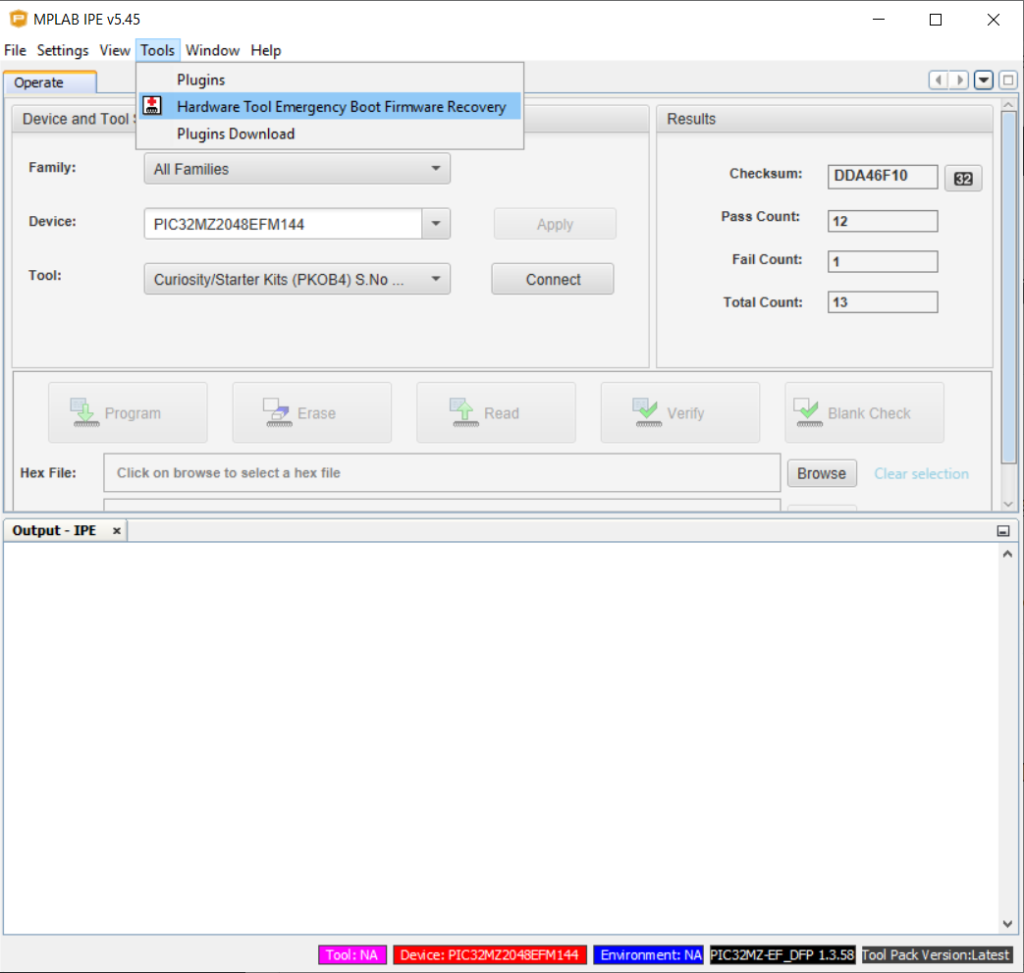
You need to reprogram the firmware of the PicKit On Board using the MPLab X IPE which is installed alongside the MPLab X IDE.

Open MPLab X IPE, open the Tools menu and select Hardware Tool Emergency Boot Firmware Recovery

After that, closely follow the instructions and reprogram the firmware for the PicKit On Board 4 programmer.

After reflashing the PKoB4 is successful, you will be able to select the Curiosity Board in MPLab X IDE.

Posted by Uli Köhler in Electronics, Embedded

Where to set MPLab X PIC32 heap size

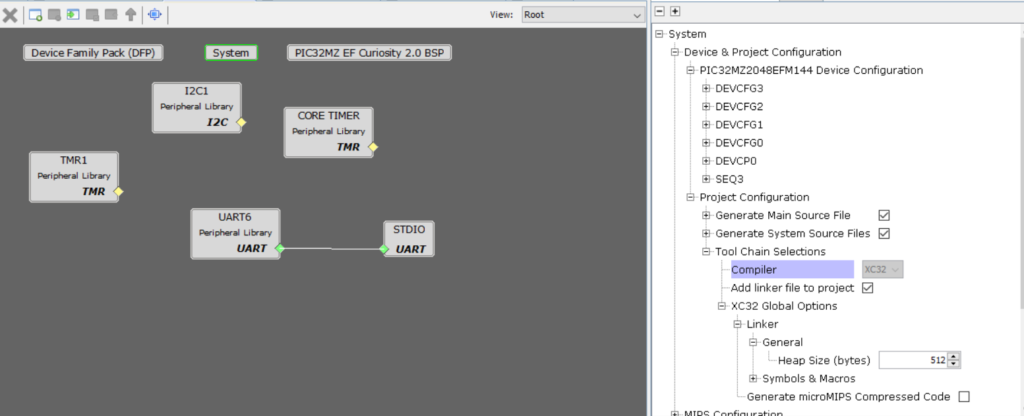
In order to set the heap size, use MPLab Harmony 3, click on System in the Project Graph, then open the tree as follows:

  • Device & Project configuration
  • Project configuration
  • Tool Chain Selections
  • XC32 Global Options
  • Linker
  • General

and set Heap Size (bytes) to the desired value.

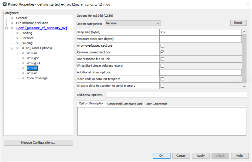
Additionally, you need to set the heap size in the project options => XC32 options => xc32-ld options:

Posted by Uli Köhler in Electronics, Embedded

Minimal ESP32 NTP client example using NTPClient_Generic and PlatformIO

Example of using NTPClient_Generic

main.cpp

#include <Arduino.h>
#include <WiFi.h>
#include <NTPClient_Generic.h>

#define TIME_ZONE_OFFSET_HRS 1 // UTC+1 for Germany, winter time
#define NTP_UPDATE_INTERVAL_MS 60000L // Update every 60s automatically
WiFiUDP ntpUDP;
NTPClient ntpClient(ntpUDP, "europe.pool.ntp.org", (3600 * TIME_ZONE_OFFSET_HRS), NTP_UPDATE_INTERVAL_MS);

void ntpUpdateTask(void* param) {
  while(true) {
    // Update NTP. This will only ACTUALLY update if
    // the NTP client has not updated for NTP_UPDATE_INTERVAL_MS
    ntpClient.update();
    vTaskDelay(1000 / portTICK_PERIOD_MS);
  }
}

void setup() {
  Serial.begin(115200);
  // Force reset Wifi to avoid failure to connect
  WiFi.disconnect(true);
  // Set hostname
  WiFi.config(INADDR_NONE, INADDR_NONE, INADDR_NONE);
  WiFi.setHostname("ESP-NTP");
  // Connect to Wifi
  WiFi.begin("MyWifiSSID", "MyWifiPassword");
  while (WiFi.status() != WL_CONNECTED) {
      delay(100);
      Serial.println("Wifi connecting...");
  }

  // Start NTP client (i.e. start listening for NTP packets)
  ntpClient.begin();
  // Create task to automatically update NTP in the background
  xTaskCreate(ntpUpdateTask, "NTP update", 2000, nullptr, 1, nullptr);
}

void loop() {
  delay(1000);
  if (ntpClient.updated()) {
    Serial.println("# Time in sync with NTP server");
  } else {
    Serial.println("# TIME NOT IN SYNC WITH NTP SERVER !");
    return; // Do not print time
  }

  Serial.println("UTC : " + ntpClient.getFormattedUTCTime());
  Serial.println("UTC : " + ntpClient.getFormattedUTCDateTime());
  Serial.println("LOC : " + ntpClient.getFormattedTime());
}

platformio.ini

[env:nodemcu-32s]
platform = espressif32
board = nodemcu-32s
framework = arduino
monitor_speed = 115200
lib_deps =
    khoih.prog/NTPClient_Generic @ ^3.2.2
    Time

Example output:

Wifi connecting...
Wifi connecting...
Wifi connecting...
# TIME NOT IN SYNC WITH NTP SERVER !
# Time in sync with NTP server
UTC : 01:22:07
UTC : 01:22:07 Sun 07 Feb 2021
LOC : 02:22:07
# Time in sync with NTP server
UTC : 01:22:08
UTC : 01:22:08 Sun 07 Feb 2021
LOC : 02:22:08
# Time in sync with NTP server
UTC : 01:22:09
UTC : 01:22:09 Sun 07 Feb 2021
LOC : 02:22:09


Posted by Uli Köhler in C/C++, ESP8266/ESP32, PlatformIO

How to get current gateway IP address on ESP8266/ESP32

In order to get the current gateway IP address on the ESP8266 or ESP32, use:

WiFi.gatewayIP();

In order to print the gateway IP address on the serial port, use

Serial.println("Gateway IP address: ");
Serial.println(WiFi.gatewayIP());

In order to get the gateway IP address as string, use

String gatewayIP = WiFi.gatewayIP().toString();


Posted by Uli Köhler in C/C++, Embedded, ESP8266/ESP32, PlatformIO

ESP32 Servo controllable via HTTP JSON API / web browser

This sketch for PlatformIO  allows you to use the ESP32 as a Servo controller (servo on pin D25) that connects to Wifi and can be controller using a simple HTTP API. The webserver is implemented using ESPAsyncWebserver. Also see ESP32 minimal JSON webserver example for PlatformIO (ESPAsyncWebserver) in case you are not familiar with that library. This example is not a finished application but a minimal starting point to build your own application.

main.cpp

#include <Arduino.h>
#include <WiFi.h>
#include <ESP32Servo.h>

#include <ESPAsyncWebServer.h>
#include <ArduinoJson.h>

AsyncWebServer server(80);

/**
 * Wait for WiFi connection, and, if not connected, reboot
 */
void waitForWiFiConnectOrReboot(bool printOnSerial=true) {
  uint32_t notConnectedCounter = 0;
  while (WiFi.status() != WL_CONNECTED) {
      delay(100);
      if(printOnSerial) {
        Serial.println("Wifi connecting...");
      }
      notConnectedCounter++;
      if(notConnectedCounter > 50) { // Reset board if not connected after 5s
          if(printOnSerial) {
            Serial.println("Resetting due to Wifi not connecting...");
          }
          ESP.restart();
      }
  }
  if(printOnSerial) {
    // Print wifi IP addess
    Serial.println("IP address: ");
    Serial.println(WiFi.localIP());
  }
}

Servo servo;

void setup() {
  ESP32PWM::allocateTimer(0);
  ESP32PWM::allocateTimer(1);
  ESP32PWM::allocateTimer(2);
  ESP32PWM::allocateTimer(3);

  Serial.begin(115200);

  WiFi.config(INADDR_NONE, INADDR_NONE, INADDR_NONE);
  WiFi.setHostname("ESP-Servo");

  WiFi.begin("MyWifiSSID", "MyWifiPassword");
  waitForWiFiConnectOrReboot();

  // Attach servo to pin 25
  servo.attach(25, 1000, 2000);
  
  // Configure HTTP routes
  server.on("/api/set-servo", HTTP_GET, [](AsyncWebServerRequest *request) {
      float value = request->arg("value").toFloat();
      servo.write(value);
      // Send {status: "ok"}
      AsyncResponseStream *response = request->beginResponseStream("application/json");
      DynamicJsonDocument json(1024);
      json["status"] = "ok";
      serializeJson(json, *response);
      request->send(response);
  });
  
  // Start webserver
  server.begin();
}

void loop() {
}

platformio.ini

[env:nodemcu-32s]
platform = espressif32
board = nodemcu-32s
framework = arduino
monitor_speed = 115200
lib_deps =
    ESP Async [email protected]
    [email protected]
    ESP32Servo

How to use

Insert your Wifi credentials in the line

WiFi.begin("MyWifiSSID", "MyWifiPassword");

and upload the firmware. Now open http://[ip address of the ESP32]/api/set-servo?value=0.0. Note that in the current version of the firmware, you can not use value=10 but you must use value=10.0.

Posted by Uli Köhler in ESP8266/ESP32, PlatformIO

ESP32 minimal WebSocket example (ESPAsyncWebserver / PlatformIO)

Minimal firmware to use WebSockets on the ESP32 using ESPAsyncWebserver:

main.cpp

#include <Arduino.h>
#include <WiFi.h>
#include <ESPAsyncWebServer.h>
#include <ArduinoJson.h>

AsyncWebServer server(80);
AsyncWebSocket ws("/ws");

AsyncWebSocketClient* wsClient;
 
void onWsEvent(AsyncWebSocket * server, AsyncWebSocketClient * client, AwsEventType type, void * arg, uint8_t *data, size_t len){
  if(type == WS_EVT_CONNECT){
    wsClient = client;
  } else if(type == WS_EVT_DISCONNECT){
    wsClient = nullptr;
  }
}

/**
 * Wait for WiFi connection, and, if not connected, reboot
 */
void waitForWiFiConnectOrReboot(bool printOnSerial=true) {
  uint32_t notConnectedCounter = 0;
  while (WiFi.status() != WL_CONNECTED) {
      delay(100);
      if(printOnSerial) {
        Serial.println("Wifi connecting...");
      }
      notConnectedCounter++;
      if(notConnectedCounter > 50) { // Reset board if not connected after 5s
          if(printOnSerial) {
            Serial.println("Resetting due to Wifi not connecting...");
          }
          ESP.restart();
      }
  }
  if(printOnSerial) {
    // Print wifi IP addess
    Serial.println("IP address: ");
    Serial.println(WiFi.localIP());
  }
}


void setup() { 
  Serial.begin(115200);
  WiFi.config(INADDR_NONE, INADDR_NONE, INADDR_NONE);
  WiFi.setHostname("ESP-Websocket-Test");

  WiFi.begin("MyWifiSSID", "MyWifiPassword");
  waitForWiFiConnectOrReboot();

  // Start webserver
  ws.onEvent(onWsEvent);
  server.addHandler(&ws);
  server.begin();
}

uint64_t counter = 0;
void loop() {
  // If client is connected ...
  if(wsClient != nullptr && wsClient->canSend()) {
    // .. send hello message :-)
    wsClient->text("Hello client");
  }

  // Wait 10 ms
  delay(10);
}

platformio.ini:

[env:nodemcu-32s]
platform = espressif32
board = nodemcu-32s
framework = arduino
monitor_speed = 115200
lib_deps =
    ESP Async [email protected]
    [email protected]

Python code for testing:

import websocket
ws = websocket.WebSocket()
ws.connect("ws://192.168.1.211/ws")
while True:
    result = ws.recv()
    print(result)

This will print Hello Client many times a second.

Posted by Uli Köhler in C/C++, ESP8266/ESP32, PlatformIO

How to fix ESP32 too few arguments to function ‘esp_err_t esp_wifi_sta_wpa2_ent_enable(const esp_wpa2_config_t*)’

Problem:

While trying to compile your ESP32 application, you see this compiler error:

src\main.cpp: In function 'void wifiConnectWPAEAP(const char*, const char*, const char*, const char*)':
src\main.cpp:23:32: error: too few arguments to function 'esp_err_t esp_wifi_sta_wpa2_ent_enable(const esp_wpa2_config_t*)'   esp_wifi_sta_wpa2_ent_enable();
                                ^

Solution:

Replace

esp_wifi_sta_wpa2_ent_enable();

by

esp_wpa2_config_t config = WPA2_CONFIG_INIT_DEFAULT();
esp_wifi_sta_wpa2_ent_enable(&config);
Posted by Uli Köhler in C/C++, Embedded, ESP8266/ESP32

How to fix ESP32 fatal error: ESP8266WiFi.h: No such file or directory

Problem:

While trying to compile your ESP32 application, you see this compiler error:

fatal error: ESP8266WiFi.h: No such file or directory

Solution:

ESP8266WiFi.h is the Wifi header for the ESP8266. For the ESP32, it’s named WiFi.h. In order to fix the issue, replae

#include <ESP8266WiFi.h>

by

#include <WiFi.h>
Posted by Uli Köhler in C/C++, Embedded, ESP8266/ESP32

How to set WiFi DHCP hostname on ESP32/ESP8266 (different from “espressif”)

Using ESP-IDF

ESP_ERROR_CHECK(esp_event_loop_create_default());
esp_netif_t* wifiStaNetif = esp_netif_create_default_wifi_sta();

const char* hostname = "MyESP32";
ESP_ERROR_CHECK(esp_netif_set_hostname(wifiStaNetif, hostname));

Using Arduino framework

Use

WiFi.config(INADDR_NONE, INADDR_NONE, INADDR_NONE);
WiFi.setHostname("My-ESP32-Test");

to set a custom hostname for the ESP32. The Wifi.config(...) line is required as a workaround for this bug on Github.

Posted by Uli Köhler in ESP8266/ESP32

ESP32 minimal JSON webserver example for PlatformIO (ESPAsyncWebserver)

This is my recommended starting point to get a webserver running on the ESP32 using PlatformIO:

#include <Arduino.h>
#include <WiFi.h>
#include <ESPAsyncWebServer.h>
#include <ArduinoJson.h>

AsyncWebServer server(80);

void setup() { 
  Serial.begin(115200);
  // Connect Wifi, restart if not connecting
  // https://techoverflow.net/2021/01/21/how-to-fix-esp32-not-connecting-to-the-wifi-network/
  WiFi.begin("MyWifiSSID", "MyWifiPassword");
  uint32_t notConnectedCounter = 0;
  while (WiFi.status() != WL_CONNECTED) {
      delay(100);
      Serial.println("Wifi connecting...");
      notConnectedCounter++;
      if(notConnectedCounter > 150) { // Reset board if not connected after 15s
          Serial.println("Resetting due to Wifi not connecting...");
          ESP.restart();
      }
  }
  Serial.print("Wifi connected, IP address: ");
  Serial.println(WiFi.localIP());

  // Initialize webserver URLs
  server.on("/api/wifi-info", HTTP_GET, [](AsyncWebServerRequest *request) {
      AsyncResponseStream *response = request->beginResponseStream("application/json");
      DynamicJsonDocument json(1024);
      json["status"] = "ok";
      json["ssid"] = WiFi.SSID();
      json["ip"] = WiFi.localIP().toString();
      serializeJson(json, *response);
      request->send(response);
  });

  // Start webserver
  server.begin();
}

void loop() {
  // put your main code here, to run repeatedly:
}

Remember to replace your Wifi credentials! WiFi.begin("MyWifiSSID", "MyWifiPassword");

To your platformio.ini add:

monitor_speed = 115200
lib_deps =
    ESP Async [email protected]
    [email protected]

My complete platformio.ini looks like this:

[env:nodemcu-32s]
platform = espressif32
board = nodemcu-32s
framework = arduino
monitor_speed = 115200
lib_deps =
    ESP Async [email protected]
    [email protected]

Use PlatformIO’s Upload and Monitor so you can see the IP address of the device in your Wifi network, for example:

Wifi connected, IP address: 192.168.178.90

then goto http://192.168.178.90/api/wifi-info (replace 192.168.178.90 by the IP address of the ESP32 that you can see on the command line!

You should now see JSON like:

{
     status: "ok",
     ssid: "MyWifiSSID",
     ip: "192.168.178.90"
}

Remember that you can use a browser plugin like JSON Viewer for Chrome in order to auto-format JSON documents!
Posted by Uli Köhler in ESP8266/ESP32