Uli Köhler

How to find out if Arduino framework is used using the preprocessor (PlatformIO)

You can use How to print all preprocessor flags in PlatformIO to print preprocessor flags. Note that these include the flags #defined in #includes such as Arduino.h. You can remove everything from main.cpp, however, so only the flags defined by the build environment are visible.

The Arduino-related flags are

#define ARDUINO_VARIANT "esp32"
#define ARDUINO_ARCH_ESP32 1
#define ARDUINO_PARTITION_default 1
#define ARDUINO 10812
#define ARDUINO_ESP32_DEV 1
#define ARDUINO_BOARD "Espressif ESP32 Dev Module"

So if you want a platform-independent check for Arduino, use

#ifdef ARDUINO
  // Arduino code goes here
#else
  // Non-Arduino code goes here
#else


Posted by Uli Köhler in Arduino

STM32H743 Arduino PlatformIO example: Read ADC with 16 bit resolution

This example configures ADC1 to read a 16 bit analog value of PA7 using a polled loop. The serial output is available on the STLink header.

#include <Arduino.h>
#include <stm32h7xx_hal.h>

ADC_HandleTypeDef hadc1;

static void MX_GPIO_Init(void)
{
    GPIO_InitTypeDef GPIO_InitStruct = {0};

    // Enable the GPIOA clock
    __HAL_RCC_GPIOA_CLK_ENABLE();

    /**ADC1 GPIO Configuration    
    PA7     ------> ADC1_IN7 
    */
    GPIO_InitStruct.Pin = GPIO_PIN_7;
    GPIO_InitStruct.Mode = GPIO_MODE_ANALOG;
    GPIO_InitStruct.Pull = GPIO_NOPULL;
    HAL_GPIO_Init(GPIOA, &GPIO_InitStruct);
}

static void MX_ADC1_Init(void)
{
    ADC_ChannelConfTypeDef sConfig = {0};

    hadc1.Instance = ADC1;
    hadc1.Init.ClockPrescaler = ADC_CLOCK_SYNC_PCLK_DIV4;
    hadc1.Init.Resolution = ADC_RESOLUTION_16B;
    hadc1.Init.ScanConvMode = ADC_SCAN_DISABLE;
    hadc1.Init.EOCSelection = ADC_EOC_SINGLE_CONV;
    hadc1.Init.LowPowerAutoWait = DISABLE;
    hadc1.Init.ContinuousConvMode = DISABLE;
    hadc1.Init.NbrOfConversion = 1;
    hadc1.Init.DiscontinuousConvMode = DISABLE;
    hadc1.Init.ExternalTrigConv = ADC_SOFTWARE_START;
    hadc1.Init.ExternalTrigConvEdge = ADC_EXTERNALTRIGCONVEDGE_NONE;
    //hadc1.Init.DMAContinuousRequests = DISABLE;
    hadc1.Init.Overrun = ADC_OVR_DATA_OVERWRITTEN;
    hadc1.Init.OversamplingMode = DISABLE;
    if (HAL_ADC_Init(&hadc1) != HAL_OK)
    {
        // Initialization Error
    }

    sConfig.Channel = ADC_CHANNEL_7;
    sConfig.Rank = ADC_REGULAR_RANK_1;
    sConfig.SamplingTime = ADC_SAMPLETIME_2CYCLES_5;
    sConfig.SingleDiff = ADC_SINGLE_ENDED;
    sConfig.OffsetNumber = ADC_OFFSET_NONE;
    sConfig.Offset = 0;
    if (HAL_ADC_ConfigChannel(&hadc1, &sConfig) != HAL_OK)
    {
        // Channel Configuration Error
    }
}

void setup() {
  HAL_Init();
  SystemClock_Config();
  MX_GPIO_Init();
  MX_ADC1_Init();

  Serial.begin(115200);

}

void loop() {
    HAL_ADC_Start(&hadc1); // Start ADC conversion
    HAL_ADC_PollForConversion(&hadc1, HAL_MAX_DELAY); // Wait for conversion to complete

    uint32_t adcValue = HAL_ADC_GetValue(&hadc1); // Read the ADC converted value
    Serial.printf("ADC value: %04X\n", adcValue);
}
[env:nucleo_h743zi]
platform = ststm32
board = nucleo_h743zi
framework = arduino
monitor_speed = 115200

Example output (unconnected):

ADC value: 04B6
ADC value: 049C
ADC value: 04AC
ADC value: 04AE
ADC value: 0497
ADC value: 04AF
ADC value: 04A7
ADC value: 04C6
ADC value: 0491
ADC value: 04A1
ADC value: 04AF
ADC value: 0493
ADC value: 0497
ADC value: 04AF
ADC value: 04A3
ADC value: 047D
ADC value: 04C1
ADC value: 04B1
ADC value: 04AF
ADC value: 0498
ADC value: 04A1
ADC value: 04C3
ADC value: 04AE
ADC value: 04AC
ADC value: 0489
ADC value: 0491
ADC value: 0491
ADC value: 047E
ADC value: 04B8
ADC value: 0494
ADC value: 04A5
ADC value: 0491
ADC value: 0494
ADC value: 048A
ADC value: 0499
ADC value: 0494
ADC value: 049E


Posted by Uli Köhler in Arduino, C/C++, PlatformIO, STM32

How to fix CMake build error on Ubuntu: Could NOT find HarfBuzz (missing: HarfBuzz_INCLUDE_DIR HarfBuzz_LIBRARY

Problem:

While building a software project using cmake, you see error messages like

CMake Error at /usr/share/cmake-3.25/Modules/FindPackageHandleStandardArgs.cmake:230 (message):
  Could NOT find HarfBuzz (missing: HarfBuzz_INCLUDE_DIR HarfBuzz_LIBRARY
  _HarfBuzz_REQUIRED_LIBS_FOUND)
Call Stack (most recent call first):
  /usr/share/cmake-3.25/Modules/FindPackageHandleStandardArgs.cmake:600 (_FPHSA_FAILURE_MESSAGE)
  cmake/FindHarfBuzz.cmake:153 (find_package_handle_standard_args)
  CMakeLists.txt:801 (find_package)

Solution:

Install libharfbuzz-dev

sudo apt -y install libharfbuzz-dev


Posted by Uli Köhler in CMake, Linux

How to fix CMake build error on Ubuntu: Could NOT find GLM (missing: GLM_INCLUDE_DIR GLM_VERSION)

Problem:

While building a software project using cmake, you see error messages like

CMake Error at /usr/share/cmake-3.25/Modules/FindPackageHandleStandardArgs.cmake:230 (message):
  Could NOT find GLM (missing: GLM_INCLUDE_DIR GLM_VERSION) (Required is at
  least version "0.9.8")
Call Stack (most recent call first):
  /usr/share/cmake-3.25/Modules/FindPackageHandleStandardArgs.cmake:600 (_FPHSA_FAILURE_MESSAGE)
  cmake/FindGLM.cmake:54 (FIND_PACKAGE_HANDLE_STANDARD_ARGS)
  CMakeLists.txt:751 (find_package)

Solution:

Install libglm-dev

sudo apt -y install libglm-dev


Posted by Uli Köhler in CMake, Linux

How to fix CMake build error on Ubuntu: Could NOT find GLEW (missing: GLEW_INCLUDE_DIR GLEW_LIBRARY)

Problem:

While building a software project using cmake, you see error messages like

CMake Error at /usr/share/cmake-3.25/Modules/FindPackageHandleStandardArgs.cmake:230 (message):
  Could NOT find GLEW (missing: GLEW_INCLUDE_DIR GLEW_LIBRARY)
Call Stack (most recent call first):
  /usr/share/cmake-3.25/Modules/FindPackageHandleStandardArgs.cmake:600 (_FPHSA_FAILURE_MESSAGE)
  cmake/FindGLEW.cmake:38 (find_package_handle_standard_args)
  CMakeLists.txt:743 (find_package

Solution:

Install libglew-dev

sudo apt -y install libglew-dev


Posted by Uli Köhler in CMake, Linux

How to plot cumulative Gitlab group members using matplotlib

This is based on my previous post to find the group ID by group name.

import matplotlib.pyplot as plt
import matplotlib.dates as mdates
from datetime import datetime
import gitlab

def plot_cumulative_members(members):
    # Convert date strings to datetime objects and sort
    dates = sorted([datetime.strptime(member["access_granted_date"], '%Y-%m-%dT%H:%M:%S.%fZ') for member in members])

    # Calculate cumulative count
    cumulative_count = range(1, len(dates) + 1)

    # Plotting
    plt.figure(figsize=(10, 6))
    plt.plot(dates, cumulative_count, marker='o')
    plt.title('Cumulative Number of Users in GitLab Group Over Time')
    plt.xlabel('Date')
    plt.ylabel('Cumulative Number of Users')
    plt.grid(True)
    plt.gca().xaxis.set_major_formatter(mdates.DateFormatter('%Y-%m-%d'))
    plt.gca().xaxis.set_major_locator(mdates.YearLocator())
    plt.gcf().autofmt_xdate()  # Rotation
    plt.show()

group_id = get_gitlab_group_id("Protectors of the Footprint Realm", 'glpat-...')
members = get_group_members(group_id, 'glpat-...')
with plt.xkcd():
    plot_cumulative_members(members)

Posted by Uli Köhler in GitLab, Python

How to find Gitlab group ID using Gitlab API via python-gitlab

pip install python-gitlab
import gitlab

def get_gitlab_group_id(group_name, access_token):
    # Initialize a GitLab instance with your private token
    gl = gitlab.Gitlab('https://gitlab.com', private_token=access_token)

    # Search for groups by name
    groups = gl.groups.list(search=group_name)
    for group in groups:
        if group.name == group_name or group.path == group_name:
            return group.id

    raise ValueError("Group not found")

# Usage example
group_id = get_gitlab_group_id("Protectors of the Footprint Realm", 'glpat-yykIsrTg6RyKcFAvd2os')

group_id will be an integer, for example 6604163

Posted by Uli Köhler in GitLab, Python

Where does matplotlib look for fonts on Linux?

Find out using

import matplotlib.font_manager
print(matplotlib.font_manager.X11FontDirectories)

On my Ubuntu 22.04, this lists:

['/usr/X11R6/lib/X11/fonts/TTF/',
 '/usr/X11/lib/X11/fonts',
 '/usr/share/fonts/',
 '/usr/local/share/fonts/',
 '/usr/lib/openoffice/share/fonts/truetype/',
 '~/.local/share/fonts',
 '~/.fonts']


Posted by Uli Köhler in Python

How to generate random strings that look like Gitlab access tokens

import secrets
import string

def generate_gitlab_access_token(length=20):
    characters = string.ascii_letters + string.digits + '_'
    token = ''.join(secrets.choice(characters) for _ in range(length))
    return f'glpat-{token}'

# Example usage:
access_token = generate_gitlab_access_token()
print(access_token)

Example output:

glpat-yykIsrTg6RyKcFAvd2os


Posted by Uli Köhler in GitLab, Python

How to fix matplotlib findfont: Font family ‘xkcd’ not found on Ubuntu 22.04+

Problem:

While plotting an XKCD-style plot using matplotlib, you see the following error messages:

findfont: Font family 'xkcd' not found.
findfont: Font family 'xkcd Script' not found.
findfont: Font family 'Comic Neue' not found.
findfont: Font family 'Comic Sans MS' not found.

Solution:

Install the Humor Sans font using

sudo apt -y install font-humor-sans

Additionally, you need to remove the matplotlib font cache:

rm -rf ~/.cache/matplotlib


Posted by Uli Köhler in Linux, Python

How to hide password strength meter with PrimeNG [p-password] InputPassword

Use [feedback]="false" to hide the strength meter:

<p-password [feedback]="false" [(ngModel)]="value"></p-password>


Posted by Uli Köhler in Angular

Minimal component count voltage-controlled duty cycle PWM circuit

When given a stimulus PWM e.g. from a microcontroller or other oscillator, this simple circuit allows using a capacitor’s time constant to generate

The main trick here is to use the Schottky diode D1 to discharge the capacitor quickly when the stimulus PWM is low, and charging it slowly via R1.

The values used here are for MHz-frequency PWMs. Choose a R-C time constant suitable for your PWM frequency (R1 / C1). A good place to start is with the R-C time constant at 0.5 * period with period = 1/frequency. In general, you want the capacitor to be almost fully charged when the positive duty cycle period is over. You can compute the time constant using Wolfram Alpha.

If you are using larger capacitors than ~10nF, you should add a resistor in series with D1 to avoid killing the MCU output stage by dumping all the capacitor’s energy into it. Compute the resistor so that the maximum allowable input current equals the capacitor charge voltage (= typically the MCU supply voltage) minus the minimum diode forward voltage, across the resistor. This is a conservative choice, but you should start from there.

Keep in mind that the charge voltage is not linear, therefore the resulting voltage-controlled duty cycle is not linear with input voltage.

In order to allow a high duty cycle PWM output, the stimulus PWM should have almost 100% duty cycle. There must be enough time in the off-duty-cycle to properly discharge the capacitor via the Schottky diode.

Consider adding hysteresis to the comparator to avoid output oscillation.

The choice of diode doesn’t matter too much. Schottky diodes should be preferred because they tend discharge the capacitor more completely within less time: A 1N4148 would only discharge the capacitor to Vf~=0.7V, whereas the rest of the charge would have to flow out via the resistor. With Schottky diodes, this forward voltage is just 0.3V, in effect allowing a higher maximum duty cycle.

A single R/C/D circuit can be used to power multiple comparators, allowing multiple channels of voltage controlled PWM.
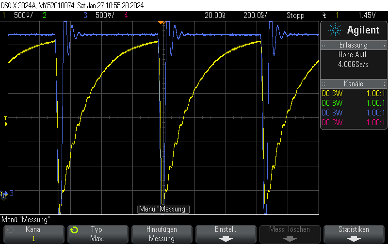
Measurement results

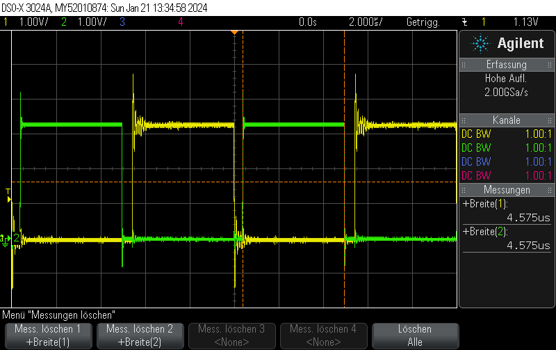
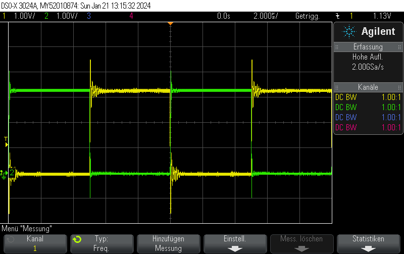
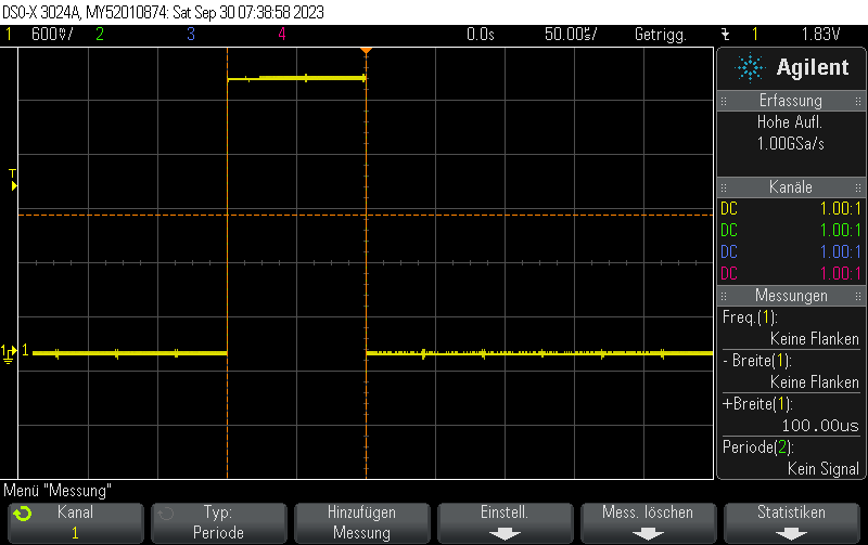
This is what it actually looks like. The voltage rise on the capacitor is fairly linear, it just appears to be oscillating due to inadequate effort being put into measuring this circuit. Keep in mind that this is not an ultra-precision circuit and in practice it’s not completely monotonous and certainly not linear in voltage.

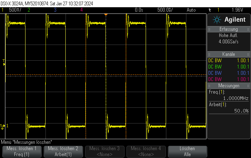
The stimulus is given in blue. It’s a 4-bit 1.5MHz PWM with 15/16 duty cycle.

The capacitor voltage, which can be fed into the comparator, is shown in yellow.


Posted by Uli Köhler in Electronics

ESP32-S3 multiple frequency PWM output using the LEDC driver

This Arduino/PlatformIO firmware outputs 50% duty cycle PWM at different frequencies on multiple pins using the LEDC PWM driver, utilizing all four timers:

  • 10 kHz on GPIO10
  • 100 kHz on GPIO11
  • 500 kHz on GPIO12
  • 1 MHz on GPIO13
#include <Arduino.h>
#include <driver/ledc.h>

void setup() {

  ledc_timer_config_t ledc_timer1 = {
      .speed_mode       = LEDC_LOW_SPEED_MODE,
      .duty_resolution  = LEDC_TIMER_1_BIT,
      .timer_num        = LEDC_TIMER_0,
      .freq_hz          = 10000,
      .clk_cfg          = LEDC_AUTO_CLK
  };
  ESP_ERROR_CHECK(ledc_timer_config(&ledc_timer1));

  ledc_timer_config_t ledc_timer2 = {
      .speed_mode       = LEDC_LOW_SPEED_MODE,
      .duty_resolution  = LEDC_TIMER_1_BIT,
      .timer_num        = LEDC_TIMER_1,
      .freq_hz          = 100000,
      .clk_cfg          = LEDC_AUTO_CLK
  };
  ESP_ERROR_CHECK(ledc_timer_config(&ledc_timer2));

  ledc_timer_config_t ledc_timer3 = {
      .speed_mode       = LEDC_LOW_SPEED_MODE,
      .duty_resolution  = LEDC_TIMER_1_BIT,
      .timer_num        = LEDC_TIMER_2,
      .freq_hz          = 500000,
      .clk_cfg          = LEDC_AUTO_CLK
  };
  ESP_ERROR_CHECK(ledc_timer_config(&ledc_timer3));

  ledc_timer_config_t ledc_timer4 = {
      .speed_mode       = LEDC_LOW_SPEED_MODE,
      .duty_resolution  = LEDC_TIMER_1_BIT,
      .timer_num        = LEDC_TIMER_3,
      .freq_hz          = 1000000,
      .clk_cfg          = LEDC_AUTO_CLK
  };
  ESP_ERROR_CHECK(ledc_timer_config(&ledc_timer4));


  /**
   * @brief Configure LEDC output channels
   */

  ledc_channel_config_t ledc1 = {
      .gpio_num       = GPIO_NUM_10,
      .speed_mode     = LEDC_LOW_SPEED_MODE,
      .channel        = LEDC_CHANNEL_0,
      .intr_type      = LEDC_INTR_DISABLE,
      .timer_sel      = LEDC_TIMER_0,
      .duty           = 1, // Set duty to 50%
      .hpoint         = 0
  };
  ESP_ERROR_CHECK(ledc_channel_config(&ledc1));

  ledc_channel_config_t ledc2 = {
      .gpio_num       = GPIO_NUM_11,
      .speed_mode     = LEDC_LOW_SPEED_MODE,
      .channel        = LEDC_CHANNEL_1,
      .intr_type      = LEDC_INTR_DISABLE,
      .timer_sel      = LEDC_TIMER_1,
      .duty           = 1, // Set duty to 50%
      .hpoint         = 0
  };
  ESP_ERROR_CHECK(ledc_channel_config(&ledc2));

  ledc_channel_config_t ledc3 = {
      .gpio_num       = GPIO_NUM_12,
      .speed_mode     = LEDC_LOW_SPEED_MODE,
      .channel        = LEDC_CHANNEL_2,
      .intr_type      = LEDC_INTR_DISABLE,
      .timer_sel      = LEDC_TIMER_2,
      .duty           = 1, // Set duty to 50%
      .hpoint         = 0
  };
  ESP_ERROR_CHECK(ledc_channel_config(&ledc3));

  ledc_channel_config_t ledc4 = {
      .gpio_num       = GPIO_NUM_13,
      .speed_mode     = LEDC_LOW_SPEED_MODE,
      .channel        = LEDC_CHANNEL_3,
      .intr_type      = LEDC_INTR_DISABLE,
      .timer_sel      = LEDC_TIMER_3,
      .duty           = 1, // Set duty to 50%
      .hpoint         = 0
  };
  ESP_ERROR_CHECK(ledc_channel_config(&ledc4));

}

void loop() {
  // Nothing to do here
  delay(1000);
}

GPIO10

GPIO11

GPIO12

GPIO13

Posted by Uli Köhler in Arduino, ESP8266/ESP32, PlatformIO

How to set OPKG HTTP/HTTPS proxy sever

export https_proxy=http://10.1.2.3:8080/
export http_proxy=http://10.1.2.3:8080/
opkg update


Posted by Uli Köhler in OpenWRT

ESP32(-S3) ADC1 ESP-IDF minimal oneshot example with curve calibration

#include <esp_adc/adc_oneshot.h>
#include <esp_adc/adc_cali.h>
#include <esp_adc/adc_cali_scheme.h>


adc_oneshot_unit_handle_t adc1_handle = nullptr;
adc_cali_handle_t adc_cali_channel_handle = nullptr;

void InitADC() {
    //-------------ADC1 Init---------------//
    adc_oneshot_unit_init_cfg_t init_config1 = {
        .unit_id = ADC_UNIT_1,
    };
    ESP_ERROR_CHECK(adc_oneshot_new_unit(&init_config1, &adc1_handle));

    //-------------ADC1 Config---------------//
    adc_oneshot_chan_cfg_t config = {
        .atten = ADC_ATTEN_DB_11,
        .bitwidth = ADC_BITWIDTH_DEFAULT, // default width is max supported width
    };
    ESP_ERROR_CHECK(adc_oneshot_config_channel(adc1_handle, ADC_CHANNEL_6, &config));

    // Initialize 
    adc_cali_curve_fitting_config_t cali_config = {
        .unit_id = ADC_UNIT_1,
        .chan = ADC_CHANNEL_6,
        .atten = ADC_ATTEN_DB_11,
        .bitwidth = ADC_BITWIDTH_DEFAULT,
    };
    ESP_ERROR_CHECK(adc_cali_create_scheme_curve_fitting(&cali_config, &adc_cali_channel_handle));


}

void ADCRead() {
    // Read raw value
    int raw = 0;
    ESP_ERROR_CHECK(adc_oneshot_read(adc1_handle, ADC_CHANNEL_6, &raw));

    // Apply calibration to value
    int voltage = 0;
    ESP_ERROR_CHECK(adc_cali_raw_to_voltage(adc_cali_channel_handle, raw, &voltage));

    printf("ADC Channel[%d] Cali Voltage: %d mV\n", ADC_CHANNEL_6, voltage);
}

Usage example:

InitADC();
while(true)
{
    ADCRead();
    // Wait for some delay before reading again
    vTaskDelay(50 / portTICK_PERIOD_MS);
}

This prints, for example:

ADC Channel[6] Cali Voltage: 163 mV


Posted by Uli Köhler in C/C++, ESP8266/ESP32

ESP32(-S3) LEDC complementary output with programmable dead time example

On the ESP32 platform, you can use the LEDC PWM driver to generate programmable dead time by setting the duty (i.e. length of pulse) and hpoint(time offset of pulse) appropriately.

#include <driver/ledc.h>
ledc_timer_config_t ledc_timer = {
    .speed_mode       = LEDC_LOW_SPEED_MODE,
    .duty_resolution  = LEDC_TIMER_8_BIT,
    .timer_num        = LEDC_TIMER_0,
    .freq_hz          = 100000,
    .clk_cfg          = LEDC_AUTO_CLK
};
ESP_ERROR_CHECK(ledc_timer_config(&ledc_timer));

uint32_t deadTime = 20; // Large value to show clearly on the oscilloscope

ledc_channel_config_t ledc_noninverted_channel = {
    .gpio_num       = GPIO_NUM_10,
    .speed_mode     = LEDC_LOW_SPEED_MODE,
    .channel        = LEDC_CHANNEL_0,
    .intr_type      = LEDC_INTR_DISABLE,
    .timer_sel      = LEDC_TIMER_0,
    .duty           = 127-deadTime/2, // Set duty to 50%
    .hpoint         = 0
};
ESP_ERROR_CHECK(ledc_channel_config(&ledc_noninverted_channel));

ledc_channel_config_t ledc_complementary_channel = {
    .gpio_num       = GPIO_NUM_11,
    .speed_mode     = LEDC_LOW_SPEED_MODE,
    .channel        = LEDC_CHANNEL_1,
    .intr_type      = LEDC_INTR_DISABLE,
    .timer_sel      = LEDC_TIMER_0,
    .duty           = 127-deadTime/2, // Set cycle to start just after 50%
    .hpoint         = 127,
};
ESP_ERROR_CHECK(ledc_channel_config(&ledc_complementary_channel));

Posted by Uli Köhler in ESP8266/ESP32

ESP32(-S3) LEDC inverted output example

#include <driver/ledc.h>
ledc_timer_config_t ledc_timer = {
    .speed_mode       = LEDC_LOW_SPEED_MODE,
    .duty_resolution  = LEDC_TIMER_8_BIT,
    .timer_num        = LEDC_TIMER_0,
    .freq_hz          = 100000,
    .clk_cfg          = LEDC_AUTO_CLK
};
ESP_ERROR_CHECK(ledc_timer_config(&amp;ledc_timer));

ledc_channel_config_t ledc_inverted_channel = {
    .gpio_num       = GPIO_NUM_11,
    .speed_mode     = LEDC_LOW_SPEED_MODE,
    .channel        = LEDC_CHANNEL_1,
    .intr_type      = LEDC_INTR_DISABLE,
    .timer_sel      = LEDC_TIMER_0,
    .duty           = 128, // Set cycle to start just after 50%
    .hpoint         = 0,
    .flags = {.output_invert = true}
};
ESP_ERROR_CHECK(ledc_channel_config(&amp;ledc_inverted_channel));


Posted by Uli Köhler in ESP8266/ESP32

ESP32(-S3) LEDC complementary PWM example

#include <driver/ledc.h>
ledc_timer_config_t ledc_timer = {
    .speed_mode       = LEDC_LOW_SPEED_MODE,
    .duty_resolution  = LEDC_TIMER_8_BIT,
    .timer_num        = LEDC_TIMER_0,
    .freq_hz          = 100000,
    .clk_cfg          = LEDC_AUTO_CLK
};
ESP_ERROR_CHECK(ledc_timer_config(&ledc_timer));

ledc_channel_config_t ledc_noninverted_channel = {
    .gpio_num       = GPIO_NUM_10,
    .speed_mode     = LEDC_LOW_SPEED_MODE,
    .channel        = LEDC_CHANNEL_0,
    .intr_type      = LEDC_INTR_DISABLE,
    .timer_sel      = LEDC_TIMER_0,
    .duty           = 127, // Set duty to 50%
    .hpoint         = 0
};
ESP_ERROR_CHECK(ledc_channel_config(&ledc_noninverted_channel));

ledc_channel_config_t ledc_inverted_channel = {
    .gpio_num       = GPIO_NUM_11,
    .speed_mode     = LEDC_LOW_SPEED_MODE,
    .channel        = LEDC_CHANNEL_1,
    .intr_type      = LEDC_INTR_DISABLE,
    .timer_sel      = LEDC_TIMER_0,
    .duty           = 128, // Set cycle to start just after 50%
    .hpoint         = 0,
    .flags = {.output_invert = true}
};
ESP_ERROR_CHECK(ledc_channel_config(&ledc_inverted_channel));

Posted by Uli Köhler in ESP8266/ESP32

ESP32 rmt_tx sync manager minimal example

See ESP32 rmt_tx simple pulse example (ESP-IDF) for an example without sync manager

#include <driver/rmt_tx.h>
rmt_channel_handle_t channel;
rmt_tx_channel_config_t tx_chan_config = {
    .gpio_num = GPIO_NUM_19,          // GPIO number
    .clk_src = RMT_CLK_SRC_DEFAULT,   // select source clock
    .resolution_hz = 1 * 1000 * 1000, // 1 MHz resolution
    .mem_block_symbols = 64,          // memory block size, 64 * 4 = 256 Bytes
    .trans_queue_depth = 1,           // set the number of transactions that can pend in the background
};
ESP_ERROR_CHECK(rmt_new_tx_channel(&tx_chan_config, &channel));
ESP_ERROR_CHECK(rmt_enable(channel));

rmt_symbol_word_t txdata[64];
txdata[0] = {
    .duration0 = 100,
    .level0 = 1,
    .duration1 = 0,
    .level1 = 0,
};

// install sync manager
rmt_channel_handle_t tx_channels[] = {channel};
rmt_sync_manager_handle_t synchro = NULL;
rmt_sync_manager_config_t synchro_config = {
    .tx_channel_array = tx_channels,
    .array_size = sizeof(tx_channels) / sizeof(rmt_channel_handle_t),
};
ESP_ERROR_CHECK(rmt_new_sync_manager(&synchro_config, &synchro));

// Create simple encoder
rmt_copy_encoder_config_t encoder_config;
rmt_encoder_handle_t encoder;
ESP_ERROR_CHECK(rmt_new_copy_encoder(&encoder_config, &encoder));

rmt_transmit_config_t tx_config = {
    .loop_count = 0, // no transfer loop
};

while(true)
{
    ESP_ERROR_CHECK(rmt_transmit(channel, encoder, pulseRMT, 1*sizeof(rmt_symbol_word_t), &tx_config));
    // Wait for one second
    vTaskDelay(10 / portTICK_PERIOD_MS);
}


Posted by Uli Köhler in Allgemein, ESP8266/ESP32

ESP32 rmt_tx simple pulse example (ESP-IDF)

In contrast to our previous example from  ESP32 RMT pulse generation minimal example using Arduino &#038; PlatformIO this example uses the new rmt_tx API.

#include <driver/rmt_tx.h>
rmt_channel_handle_t channel;
rmt_tx_channel_config_t tx_chan_config = {
    .gpio_num = GPIO_NUM_19,          // GPIO number
    .clk_src = RMT_CLK_SRC_DEFAULT,   // select source clock
    .resolution_hz = 1 * 1000 * 1000, // 1 MHz resolution
    .mem_block_symbols = 64,          // memory block size, 64 * 4 = 256 Bytes
    .trans_queue_depth = 1,           // set the number of transactions that can pend in the background
};
ESP_ERROR_CHECK(rmt_new_tx_channel(&tx_chan_config, &channel));
ESP_ERROR_CHECK(rmt_enable(channel));

rmt_symbol_word_t txdata[64];
txdata[0] = {
    .duration0 = 100,
    .level0 = 1,
    .duration1 = 0,
    .level1 = 0,
};

// Create simple encoder
rmt_copy_encoder_config_t encoder_config;
rmt_encoder_handle_t encoder;
ESP_ERROR_CHECK(rmt_new_copy_encoder(&encoder_config, &encoder));

rmt_transmit_config_t tx_config = {
    .loop_count = 0, // no transfer loop
};

while(true)
{
    ESP_ERROR_CHECK(rmt_transmit(channel, encoder, pulseRMT, 1*sizeof(rmt_symbol_word_t), &tx_config));
    // Wait for one second
    vTaskDelay(10 / portTICK_PERIOD_MS);
}

Result:

Posted by Uli Köhler in ESP8266/ESP32